User footfall sensing control system for treadmill exercise machines

a control system and treadmill technology, applied in sport apparatus, gymnastics, clubs, etc., can solve the problems of large majority of treadmill exercise machines not including, use of treadmill exercise machines, and prior art commercial failur

Inactive Publication Date: 2013-07-09
BRUNTS RANDALL THOMAS
View PDF23 Cites 94 Cited by
  • Summary
  • Abstract
  • Description
  • Claims
  • Application Information

AI Technical Summary

Benefits of technology

[0021]In accordance with one embodiment, a control system measures the position of user footfalls on a tread belt of a treadmill exercise machine and employs the measurements to adjust tread belt speed. The control system adjusts tread belt speed in such a way as to keep the user appropriately positioned on the tread base as he or she changes speed relative to the tread belt. The control system incorporates improved means of sensing foot position as well as improved means of using foot position measurements to control tread belt speed.

Problems solved by technology

Many users dislike using treadmill exercise machines, however.
Despite these disclosures, the greatest majority of treadmill exercise machines do not incorporate automatically adjusted tread belt speed controls.
The prior art has been commercially unsuccessful due to performance limitations and excessive production costs.
However, accurate sensing of actual user position is complicated by the nature of human walking and running motion.
The result will be an unpredictable error in the user position control value of the disclosed systems.
Control signal error is a principle limiter of performance in feedback control systems, often leading to instability.
Additionally, incremental speed adjustments based on position zones or trigger lines result in slow, imprecise responses to user speed changes.
However, in-so-far as they protrude above the tread belt level, they may be perceived as non-aesthetic, they may be subject to obstruction by dirt or other objects, and they may be subject to damage due to their exposed position.
Control signal delay is a principle limiter of performance in feedback control systems.
However, fixed acceleration rates are a crude form of control which severely limits the responsiveness of belt speed to changes in user motion.
Further, the control algorithm is subject to many forms of error based on variation in user stride styles, user exercise rates, and user size.
Pressure sensors may also be expensive and subject to excessive wear.
A manual selection may be inconvenient or confusing to the user.
Further, two configurations may not allow for optimum control system performance in all modes of use.
Finally, manual selection of control system parameters may not be a practical means to optimally set parameters for all operating conditions.
This new sensor type will suffer from the same unpredictable sensing errors as other whole-body sensing methods, and thus will not provide an acceptable performance.
However, the large number of sensors required to achieve reasonably accurate measurements limit economic viability, reliability, and performance of the disclosed system.
However, the edge placement of sensors increases the total number of sensors required and limits sensor accuracy.
Thus the disclosed system will not provide an acceptable performance.
It will also still suffer from performance variations due to variations in user size and user stride style.
These omissions limit the ability of one skilled in the art to use the disclosed devices in practical applications.
Resulting values will vary unpredictably based on user running style due to torques from user impact with the tread deck.
Moreover, the system describes no means to estimate user position as the user's feet impact upon, translate upon, and leave the running surface during the course of a running or walking stride.
Further, the disclosed sensors may be expensive and subject to excessive wear.
Such erroneous reading will result in large and unpredictable error signals which will disrupt the operation of any speed control system.
The prior art also lacks any means to determine foot position more precisely than the spacing of foot sensors.
This shortcoming reduces system performance for any sensor arrangement, or alternately, increases system cost for any desired performance level.

Method used


Image

  • User footfall sensing control system for treadmill exercise machines
  • User footfall sensing control system for treadmill exercise machines
  • User footfall sensing control system for treadmill exercise machines

Examples


first embodiment

FIG. 11

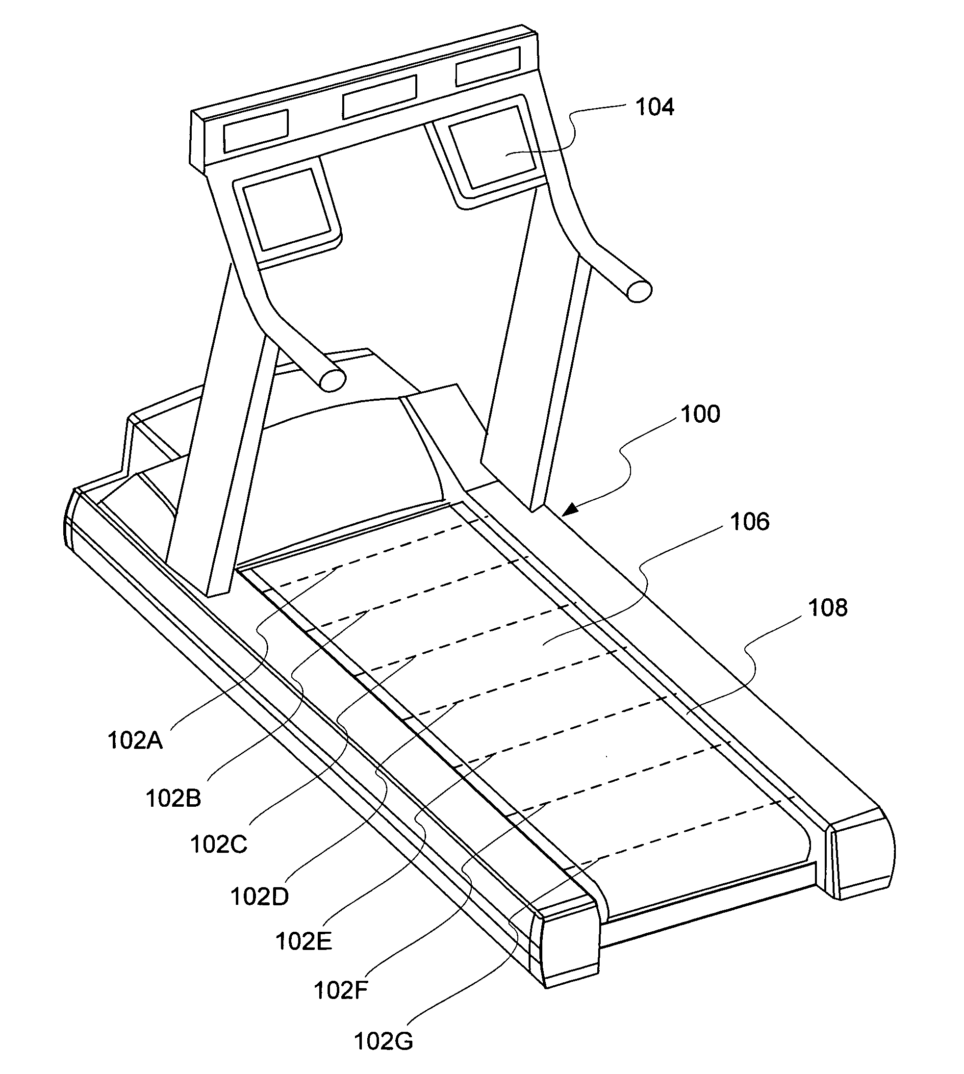
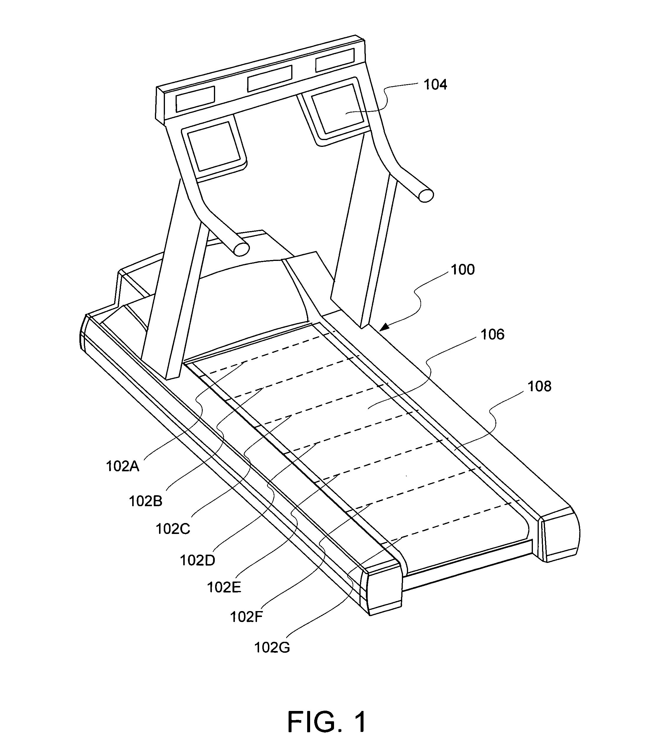
[0045]FIG. 1 shows the basic appearance of an exercise treadmill device 100 according to a first embodiment. Treadmill 100 includes a user input device 104. Treadmill 100 also includes a series of foot sensor elements 102A to 102G, spanning the width of a tread base 108. A tread belt 106 lays on top of tread base 108 and forms a continuous loop extending beneath tread base 108. A user of treadmill 100 would walk or run on top of tread belt 106 in the direction facing toward input device 104 as the top surface of tread belt 106 moves rearward.

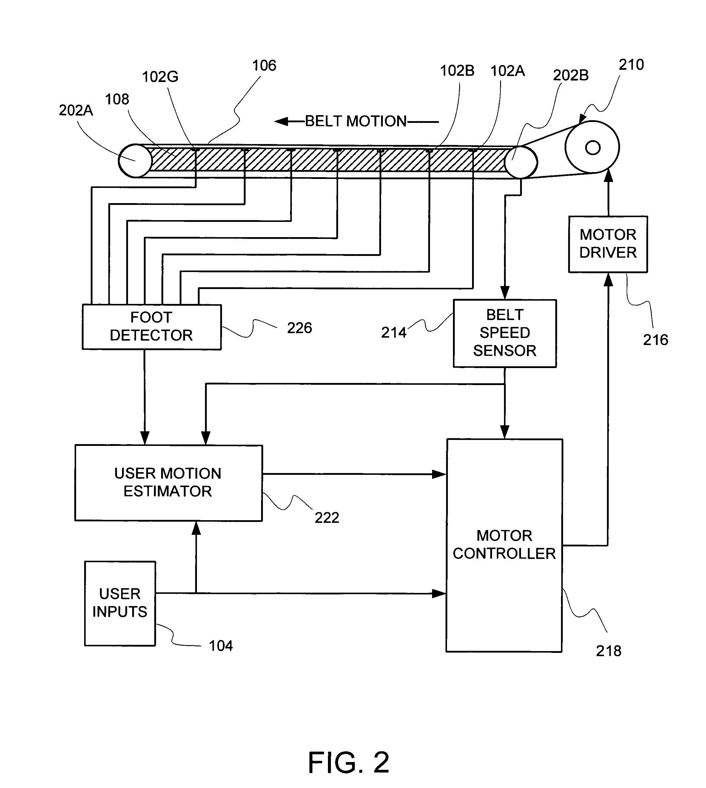
System Block Diagram—FIG. 2

[0046]FIG. 2 is a system block diagram representing the treadmill control system of one embodiment. Unless otherwise indicated, components of the system block diagram may be implemented as hardware devices, software routines, or employing any other type of compute mechanism that successfully implements the defined operations. The information values, which may also be called signals, states, or variables, which p...


PUM


Abstract

An improved treadmill control system which adjusts the speed of a moving tread belt to follow user motions. Equipment includes a tread base supporting a moving tread belt upon which a user can run or walk, a motor assembly and motor driver to move the tread belt, a plurality of foot sensors, a tread belt motion sensor, a measurement system to estimate user motion based on foot and tread belt sensor signals, and a motor controller to adjust motor assembly speed based on estimates of user motion. The system is capable of making improved user motion estimates and of using them to provide improved belt speed control. In one embodiment, user position, speed, and acceleration are estimated at each user footfall while estimates are continually revised between footfalls. In one embodiment, foot sensors are capacitive proximity sensors which are effective, fully concealable, and economical.

Description

CROSS-REFERENCE TO RELATED APPLICATIONS[0001]Not ApplicableFEDERALLY SPONSORED RESEARCH[0002]Not ApplicableSEQUENCE LISTING OR A COMPUTER PROGRAM[0003]Not ApplicableBACKGROUND[0004]1. Field[0005]This disclosure relates to a control system for treadmill exercise machines with a fixed tread base and a moving tread belt upon which a user runs or walks. The disclosed device detects the position and time of user footfalls on the tread belt and adjusts tread belt speed to maintain the user's position relative to the fixed tread base.[0006]2. Prior Art[0007]Individuals commonly use treadmill exercise machines incorporating a moving belt over a tread base as a means of exercise similar to walking or running, but in a fixed location. Many users dislike using treadmill exercise machines, however. One reason is that they must manually set an exercise pace and then match that pace in order to stay safely centered on the tread base. This means of control is dissimilar to normal walking or runnin...

Claims


Application Information

Patent Timeline
Patent Type & Authority Patents(United States)
IPC IPC(8): A63B71/00
CPCA63B22/0242A63B24/0087A63B2022/025A63B2024/0093A63B2220/62A63B2220/13A63B2220/22A63B2220/30A63B2208/14A63B22/025
Inventor BRUNTS, RANDALL THOMAS
Owner BRUNTS RANDALL THOMAS
Why Eureka
Try Eureka