ECP terminal mode operation

a terminal mode and brake system technology, applied in the direction of brake systems, process and machine control, instruments, etc., can solve the problems of new dilemmas in the process and the train system, and affecting the operation of the railroad

Active Publication Date: 2013-07-09
NEW YORK AIR BRAKE CORP
View PDF17 Cites 4 Cited by
  • Summary
  • Abstract
  • Description
  • Claims
  • Application Information

AI Technical Summary

Benefits of technology

[0004]The present method allows an ECP train to transition to and from main line operation from and to yard operation where only a subset of the overall functional control is required. In such situations, the system control capability will provide an increase in performance reliability based on the operating conditions of a given zone and or operation constraint.
[0012]The current American Association of Railroads (AAR) ECP specifications and as a result, current technologies require the ECP system to be either completely active or completely inactive. As a result, if it is desirable to disable ECP for a brief train movement, the ECP system must be re-initialized as the make-up and geometry of the train information is lost in the inactive state. This present method of ECP train brake control allows the ECP system to be placed in a semi-active state where full operational control of the ECP devices on the cars is disabled, and then when desired, the system can be transitioned back to the original state without having to be re-initialized.

Problems solved by technology

This interruption would be costly in regard to the lost time to stop and restart the loading or unloading process.
The ECP train-lined network operating within this environment brings a new dilemma to this process and the train system.
These events, although mandatory for mainline operation, may not be relevant for loading, unloading or yard operation, and as a result, create a hindrance to railroad operation where train stoppages are not desirable.
As a result, if it is desirable to disable ECP for a brief train movement, the ECP system must be re-initialized as the make-up and geometry of the train information is lost in the inactive state.

Method used


Image

  • ECP terminal mode operation
  • ECP terminal mode operation
  • ECP terminal mode operation

Examples


Embodiment Construction

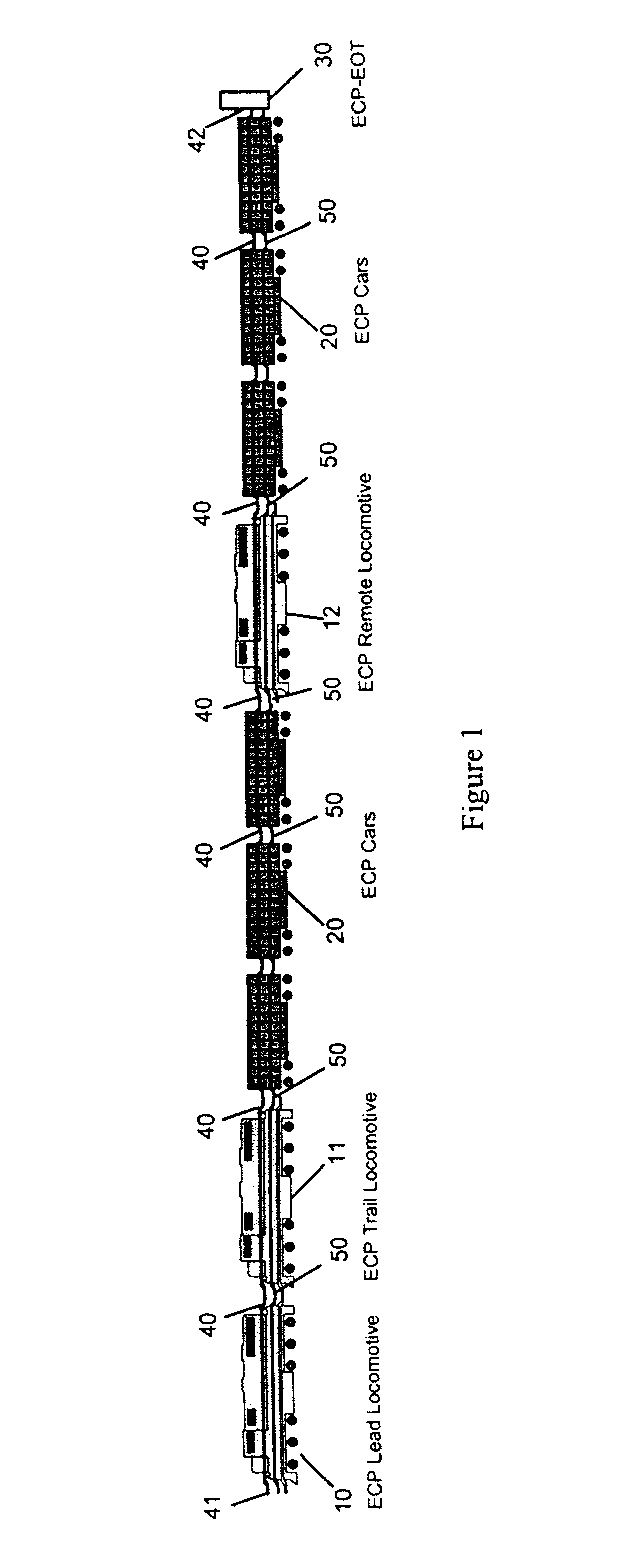
[0019]Referring to FIG. 1, an ECP train includes a lead locomotive 10 connected to a trail locomotive 11, to a remote locomotive 12 and rail cars 20 by an electrical train-line 40 and a pneumatic brake line 50. A head end train-line termination HETT 41 is provided on the head end unit HEU on the lead locomotive 10 and an end of train-line termination EOTT or ECP-EOT beacon 42 is provided at ECP end of train device (EOT) 30 on the last car.

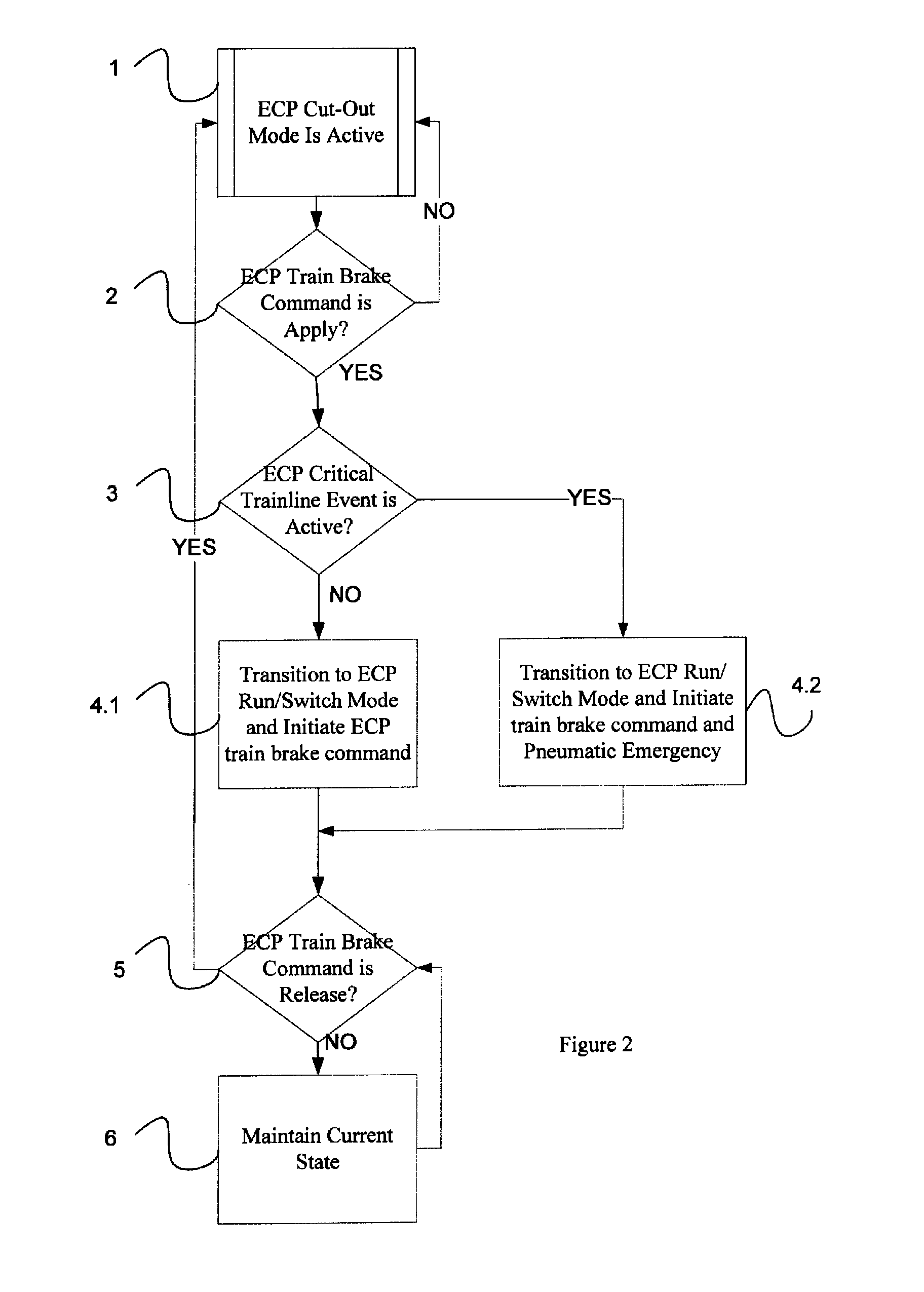
[0020]Referring to FIG. 2, upon receipt of a train brake release command from the operator or equivalent at 5, the ECP system controller or head end unit HEU shall command the ECP brake control devices located within the train to cut-out mode or inactive state at 1. In the cut-out mode, the train brakes are released and ECP mode inactive state, which renders the electronic train brake control temporarily disabled. During this operating condition, the HEU will maintain train-line power to maintain battery charging to the ECP car control devices CCDs...


PUM


Abstract

The present method operates an electrically controlled pneumatic (ECP) brake system that includes a system controller and a plurality of ECP devices on a train, in a semi-active mode between an active mode and an in active mode. The method includes setting the system controller to the semi-active mode if the ECP brake command is release; and setting the released ECP devices to the inactive state by the system controller when entering the semi-active mode. The ECP devices are set to an active state and to apply the brake by the system controller in response to an ECP brake command of apply. The ECP devices are reset to release and then to the inactive state by the system controller in response to an ECP brake command of release.

Description

[0001]This application is a U.S. Patent Application that relies for priority under 35 U.S.C. 120 on Provisional Application Ser. No. 61 / 260,181 filed on Nov. 11, 2009, which is incorporated herein by reference.BACKGROUND AND SUMMARY[0002]The present disclosure is directed to electrically controlled pneumatic (ECP) brake systems and more specifically to a semi-active mode of the system between the active mode and the inactive mode.[0003]The present method manages ECP equipped trains in situational environments where unrequested train stoppage due to detection of on-board equipment failure negatively impacts overall railroad operations. Understanding that trains are a component of a larger overall system operation which covers territory from departure to final destination there is a need to isolate the standard mainline operational requirements and enable specialized local operational requirements specific to the local railroad yard and or facilities.[0004]The present method allows an...

Claims


Application Information

Patent Timeline
Patent Type & Authority Patents(United States)
IPC IPC(8): B60T13/00B60T13/66G06F17/00G05D13/34
CPCB60T17/228B60T13/665
Inventor MARRA, JON M.LADUC, JOHN W.STEVENS, DALE R.
Owner NEW YORK AIR BRAKE CORP
Why Eureka
Try Eureka