Apparatus and method for mounting a plumbing fixture

a technology for plumbing fixtures and apparatuses, which is applied in the field of apparatus and methods for mounting plumbing fixtures, can solve the problems of not providing, to the inventor's knowledge, a commercially viable system, and failing to provide a system that can be used with generic faucet fixtures, so as to facilitate manual rotation of rods

Inactive Publication Date: 2013-07-23
JULIAN BRIAN
View PDF8 Cites 3 Cited by
  • Summary
  • Abstract
  • Description
  • Claims
  • Application Information

AI Technical Summary

Benefits of technology

[0008]In some embodiments, a thumb screw head at a second end of the rod facilitates manual rotation of the rod in the guide member.

Problems solved by technology

A number of US patents have attempted to address this problem, but these attempts inevitably remain located below the counter, and they have not provided, to the inventor's knowledge, a commercially viable system.
They have also failed to provide a system that can be used with the generic faucet fixture, as they require a proprietary faucet fixture, even though the lines that supply water to the faucets are almost completely standardized.
This limits the ability of the plumber or homeowner to avail themselves of the improvement in some of those patents in doing a retrofit.

Method used


Image

  • Apparatus and method for mounting a plumbing fixture
  • Apparatus and method for mounting a plumbing fixture
  • Apparatus and method for mounting a plumbing fixture

Examples


first embodiment

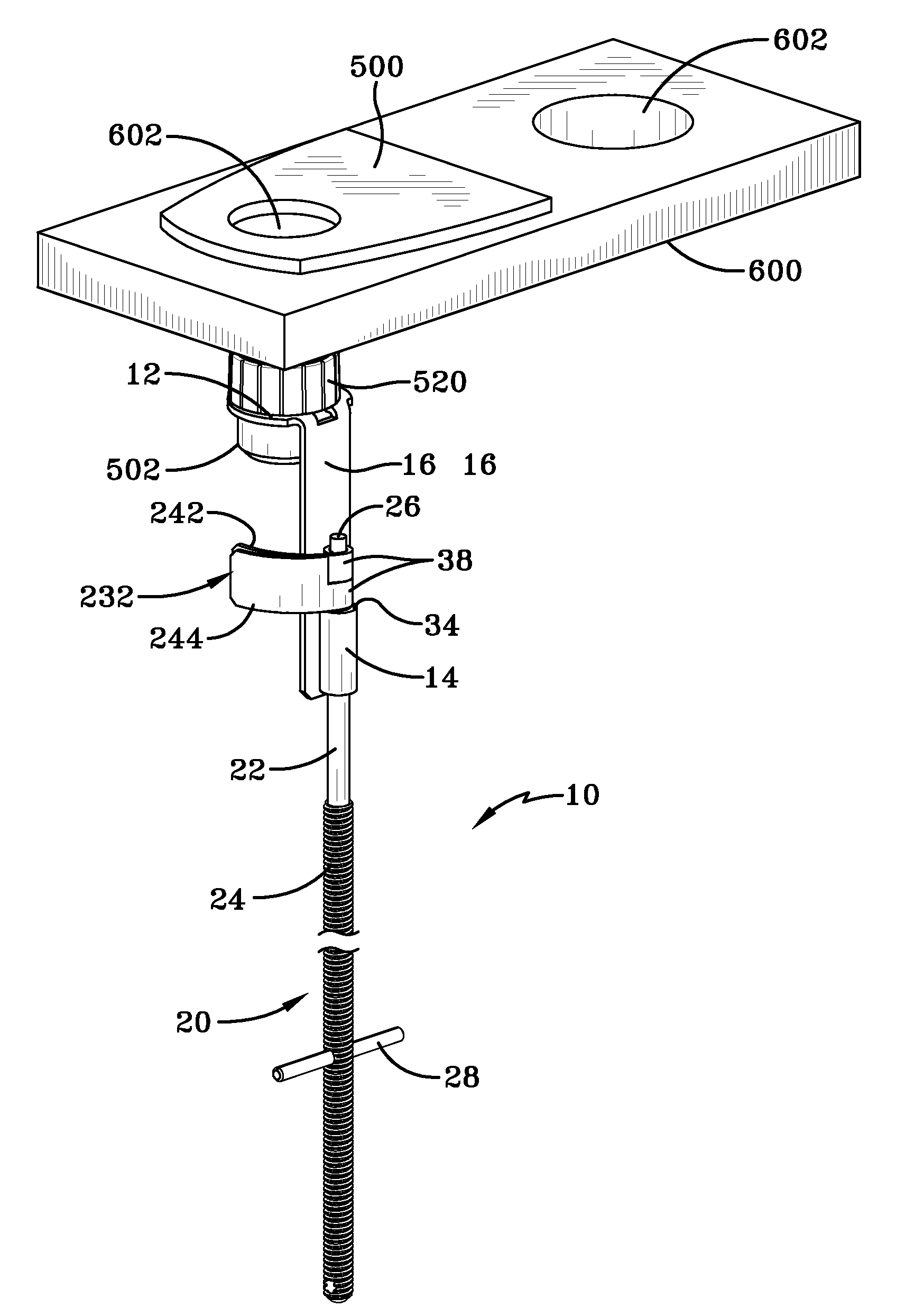
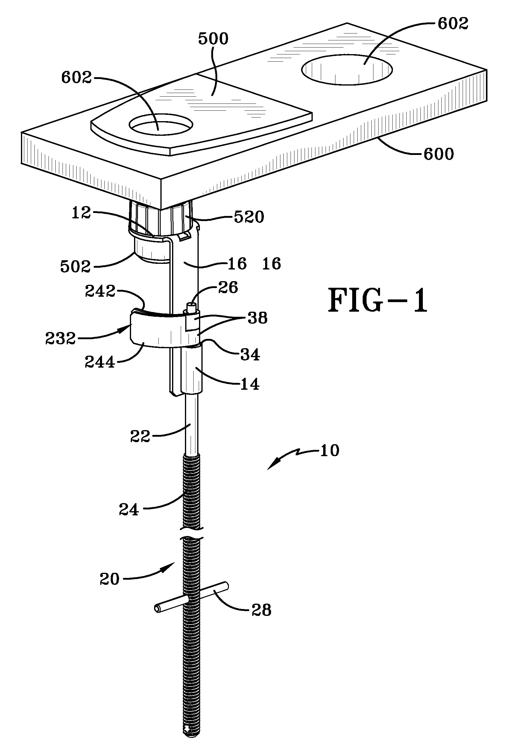
[0024]FIG. 1 is a perspective view of a first embodiment device 10 that is useful in mounting a plumbing fixture, especially a faucet, having a body 500 and an externally-threaded inlet tube 502. In FIG. 1, the body 500 is depicted schematically with the inlet tube 502 extending through a surface 600 having two holes 602. A typical surface 600 could be a counter top or a sink, but it could also be a vertical surface, such as a wall. Plumbing fixtures of this type will be known in the art and will typically have two such inlet tubes, such as inlet tube 502. The threading on the inlet tube 502 is sized to receive a standard connecting nut at an end of a supply tube (not shown in FIG. 1), which will connect the plumbing fixture to a supply of water or the like. Inlet tube 502 is also able to receive a threaded sleeve 520, one of which is shown in FIG. 1 positioned on the inlet tube, above a collar member 12 of the device 10. By omitting the supply line in FIG. 1, the device 10 is more ...

embodiment 10

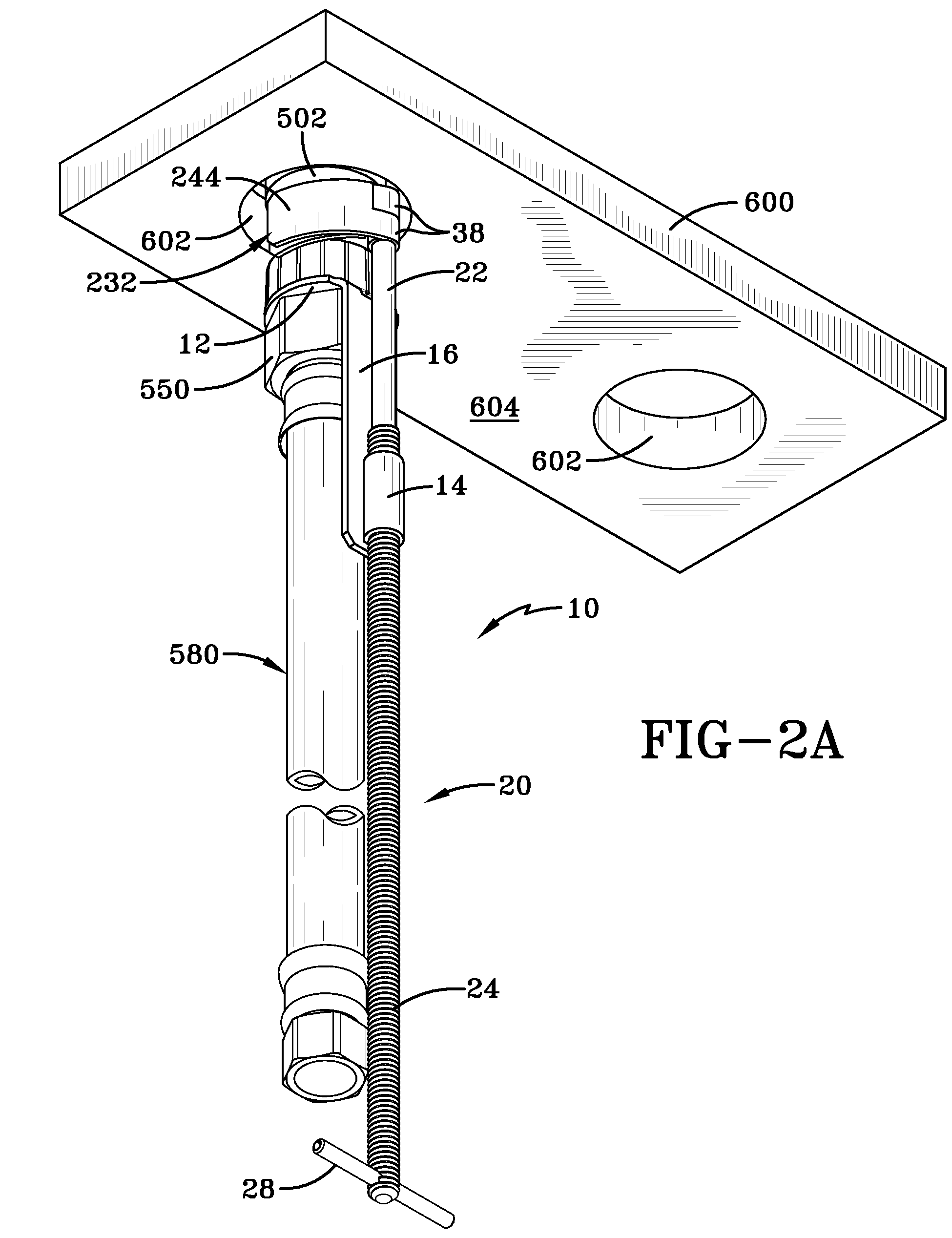
[0033]As depicted in FIG. 5, and with a device such as one of the embodiments 10, the installer passes the connecting nut end of the supply line 580 through the hole 602 from the second side 604 of the surface to the first side. Using the embodiment 10 as exemplifying the operation of any of the embodiments taught herein, the installer also positions the mounting device 10 in the hole 602, especially with the collar member 12 being on the first side and the rotating means 28 of the rod being on the second side. By placing the collar member 12 onto the inlet tube 502, the installer can secure the device 10 on the inlet tube. In some aspects of the method, this is accomplished by securing the collar member 12 by engaging a threaded sleeve 520 onto the inlet tube 502. In some other aspects, the connecting nut 550 serves this purpose when it is connected to the inlet tube. By doing this, the installer has effectively formed a connected plumbing fixture which is partially on the first si...

embodiment 210

[0035]A further embodiment 210 of the invention is presented in FIG. 7. It will be understood from the description provided that the concept of lowering a plumbing fixture through the counter top while the supply lines (or lines) are already attached is maintained in this further embodiment and that the difference in the embodiment lies primarily in the manner in which the plumbing fixture is held in place. In FIG. 7, a slightly different situation is provided for the surface 700 that is used for the mounting. Here, a thin surface 700 is depicted, such as would be provided by a stainless steel sink. Holes 702 provide very little depth, so it may be useful to insert a cylindrical insert 704 as is shown in one of the holes 702. The device 210 has a collar member 12 that is sized to be slidingly received on the inlet tube, which is not shown in FIG. 7, as this has been previously taught above. A threaded sleeve 520, which is not otherwise connected to the device 210 is shown above coll...


PUM

PropertyMeasurementUnit
lengthaaaaaaaaaa
radius of curvatureaaaaaaaaaa
radiusaaaaaaaaaa

Abstract

A device for mounting of a plumbing fixture such as a faucet or the like through a hole in a counter, a sink or the like and connection of the fixture to a supply line. A collar member of the device is slidingly retained on an inlet tube of the fixture by a connecting nut of the supply line. A rod, guided in its axial movement by a guide member that is connected to the collar member, has a flag member that is rotatable between a stowed position and a deployed position. In the stowed position, the device may be passed through the hole when connected to the plumbing fixture and the supply line. In the deployed position, the flag member increases the axial profile of the device and co-acts with the body of the plumbing fixture in retaining the plumbing fixture in the hole.

Description

CROSS-REFERENCE TO RELATED APPLICATIONS[0001]This application is a continuation-in-part of, and claims a right of priority from, PCT / US2009 / 055994, filed 4 Sep. 2009, which is, in turn, a non-provisional of, and claims a right of priority from U.S. 61 / 190,930, filed 4 Sep. 2008. The content of both applications are incorporated by reference as if fully recited herein.TECHNICAL FIELD[0002]The disclosed embodiments relate to a device which assists in the mounting of a plumbing fixture such as a faucet through a surface such as a counter top.BACKGROUND OF THE ART[0003]The mounting a faucet on a counter is conventionally accomplished by inserting the water inlet tube of the faucet down through a small hole in a counter to seat the faucet trim plate on the counter top. Next, a clamping nut is manually turned to advance along the tube until it engages the counter bottom and pulls the trim plate snugly against the counter top to clamp the faucet to the counter. Then the inlet tube is conne...

Claims


Application Information

Patent Timeline
Patent Type & Authority Patents(United States)
IPC IPC(8): E03C1/04
CPCE03C1/0401Y10T29/49947Y10T29/53987Y10T29/49963
Inventor JULIAN, BRIAN
Owner JULIAN BRIAN
Why Eureka
Try Eureka