
Angular velocity sensor

a technology of angular velocity and sensing signal, which is applied in the direction of acceleration measurement using interia forces, turn-sensitive devices, instruments, etc., can solve the problems of low and achieve efficient offset and improve the detection accuracy of angular velocity sensing signal.

Inactive Publication Date: 2013-07-23
PANASONIC CORP
View PDF21 Cites 9 Cited by
  • Summary
  • Abstract
  • Description
  • Claims
  • Application Information

AI Technical Summary

Benefits of technology

The present invention relates to an angular velocity sensor with a simplified design that reduces the impact of noise. The sensor generates two parasitic capacitances, one between the first driving electrode and the sensing electrode, and another between the second driving electrode and the sensing electrode, with opposite magnitudes. This reduces the difference between the measured capacitance and the amplitudes of the driving signals, minimizing noise. The sensor also effectively offsets the noise generated by the capacitive coupling between the first and second driving electrodes, resulting in improved detection accuracy of the angular velocity sensing signal.

Problems solved by technology

Such conventional angular velocity sensors have a problem that their angular velocity sensing signals have low detection accuracy.
As a result, the angular velocity sensing signal has low detection accuracy.

Method used


Image

  • Angular velocity sensor
  • Angular velocity sensor
  • Angular velocity sensor

Examples


Embodiment Construction

Exemplary Embodiment

[0020]An angular velocity sensor according to an exemplary embodiment of the present invention will be described as follows with reference to drawings.

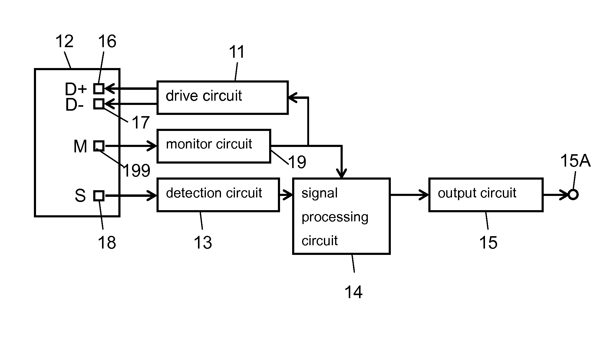
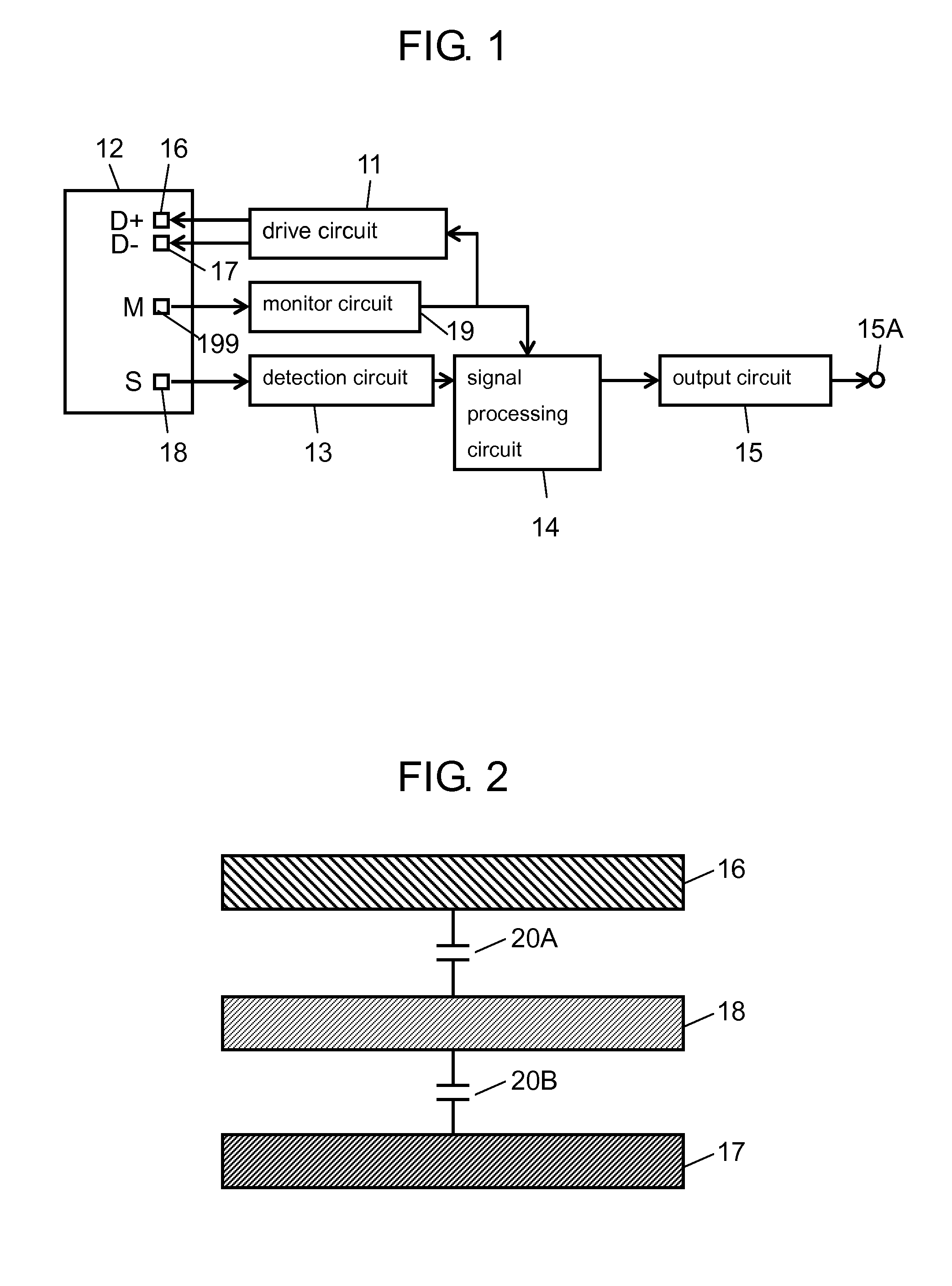
[0021]FIG. 1 is an electrical diagram of the angular velocity sensor according to the exemplary embodiment. FIG. 2 shows first and second driving electrodes and a sensing electrode in the angular velocity sensor when viewed from the above.

[0022]The angular velocity sensor includes drive circuit 11, detection device 12, and detection circuit 13. Detection device 12 vibrates in response to drive signals from drive circuit 11. Detection circuit 13 extracts a response signal from sensing electrode 18 of detection device 12, and outputs the signal. The sensor further includes signal processing circuit 14 and output circuit 15. Signal processing circuit 14 extracts an angular velocity sensing signal from the response signal and outputs the angular velocity sensing signal. Output circuit 15 includes output terminal 15A th...


PUM


Abstract

In an angular velocity sensor, there is generated a first parasitic capacitance generated between a first driving electrode and a sensing electrode, and there is generated a second parasitic capacitance generated between a second driving electrode and the sensing electrode. The ratio of the amplitude of a first drive signal to the amplitude of a second drive signal is set to the reciprocal of the ratio of the first parasitic capacitance to the second parasitic capacitance. This allows the noise contents generated by capacitive coupling to be efficiently offset, thereby improving detection accuracy of an angular velocity sensing signal.

Description

[0001]This application is a U.S. National Phase Application of PCT International Application PCT / JP2010 / 001583.TECHNICAL FIELD[0002]The present invention relates to angular velocity sensors used in digital cameras, car navigation systems, vehicle control devices, and other similar devices.BACKGROUND ART[0003]FIG. 9 is an electrical diagram of a conventional angular velocity sensor, and FIG. 10 shows first and second driving electrodes and a sensing electrode in this conventional sensor when viewed from the above.[0004]As shown in FIG. 9, the conventional angular velocity sensor includes drive circuit 1, detection device 2, and detection circuit 3. Detection device 2 vibrates in response to drive signals from drive circuit 1. Detection circuit 3 extracts a response signal from sensing electrode 8 of detection device 2, and outputs the signal. The sensor further includes signal processing circuit 4 and output circuit 5. Signal processing circuit 4 extracts an angular velocity sensing ...

Claims


Application Information

Patent Timeline
Patent Type & Authority Patents(United States)
IPC IPC(8): G01C19/56G01C19/5614
CPCG01C19/5614
Inventor SASAKI, TAKESHIKURODA, KEISUKE
Owner PANASONIC CORP
Learn More