Exercise devices with force sensors

a technology of force sensor and exercise device, which is applied in the direction of resilient force resistor, gymnastic exercise, muscle strength measurement, etc., can solve the problems of increased cost, inability to fully capture the force sensor, and many drawbacks of the force sensing function, so as to simplify the problem of data capture and calibration, easy to connect and disconnect, and easy to install and remov

Active Publication Date: 2013-07-23
KIIO
View PDF38 Cites 93 Cited by
  • Summary
  • Abstract
  • Description
  • Claims
  • Application Information

AI Technical Summary

Benefits of technology

[0007]Referring to FIGS. 1 and 2, an exemplary version of the exercise device includes a sensor body 100 having one or more force sensors therein (as seen at 102 in FIG. 3) or thereon, with means for connecting the sensor body 100 to other items—here illustrated as complementary male and female connectors 104 and 106 (best seen in FIG. 2)—situated on opposite sides of the sensor body 100. The force sensor(s)102 sense pulling and / or pushing forces exerted between the two connectors 104 and 106, and communicates the measured forces to “client” devices via wireless communications (e.g., radio frequency or infrared) or wired interconnects (e.g., Universal Serial Bus interconnects) for recording, display, and / or processing. The connectors 104 and 106 allow the sensor body 100 to interface with other components having complementarily-shaped connectors, such as the elastic member 10 (which is shown having a member length 12 terminating in a member male connector 14, an arrangement which is often formed by inserting a plug within an end of an elastic tube) and the grasping loop / handle 1000 (which is shown with a loop female connector / socket 1106 which is configured to complementarily receive the member male connector 14). Looking to FIG. 1, if the elastic member 10 extends to an anchor (such as a wall or floor), and a user grips the grasping loop 1000 and pulls, on it to extend the elastic member 10, the force sensor(s) 102 between the grasping loop 1000 and the elastic member 10 detect the force exerted along the elastic member 10 between the grasping loop 1000 and the anchor. Since a wide variety of different forms of elastic members 10 are available, as well as components configured to easily connect and disconnect to such elastic members 10 (such as grasping loops 1000, bars, harnesses, etc.), the sensor body 100 can be inserted between selected elastic members 10 and components to measure the forces generated by users during exercise. Since the sensor body 100 can be readily installed and removed between many different combinations of elastic members 10 and components, a single sensor body 100 used as a standalone device (used, for example, alternatively between two or more limbs)—or two or more sensor bodies 100, one for each limb and / or other parts of the body—can be used across all (or most) of the exercises within a user's routine to capture characteristics of the user's activity. This greatly simplifies issues with data capture and calibration, since one need not compile data collected from numerous sensors having different calibration points. Further, since the sensor body 100 is easily retrofit into existing elastic member exercise devices, a user can incorporate one or more sensor bodies into his / her equipment to add force-monitoring capabilities, and can easily remove the sensor bodies if and when desired. In addition, the cost of force-monitoring exercise equipment is greatly reduced, particularly when the low cost of elastic member exercise devices is taken into account.
[0008]Referring to FIG. 2, the male connector 104 can take the form of a neck 108 extending from the sensor body 100 along a neck axis, with the neck 108 terminating in a male plug 110 having a configuration resembling that of the member male connector 14. As a result, the male plug 110 can be removably and replaceably inserted within the loop female connector 1106 of the grasping loop 1000 in the same manner as the member male connector 14. The female connector 106 can take the form of a socket body 112 having a socket passage 114 configured similarly to the loop female connector 1106 of the grasping loop 1000, and can therefore removably and replaceably receive the member male connector 14 in complementary fashion (or the male plug 110, though the male plug 110 is not ordinarily inserted within the female connector 106 during normal use). Thus, the sensor body 100 is readily installable between the elastic member 10 and the grasping loop 1000, or between any other components having complementary connections (again, with examples being noted in the patents referenced in this document).

Problems solved by technology

In this case, the force sensing functionality suffers from many drawbacks present in the exercise devices themselves.
In particular, if the device is dedicated to the performance of only a single particular type of exercise, or a few types of exercises, the user's activity—which will often involve other types of exercise, and thus other exercise devices, as well—may not be fully captured by the force sensor.
While a user might have a number of different exercise devices, each bearing its own force sensor for monitoring activities on its particular device, such an arrangement leads to greater expense, and to difficulties with collecting and organizing data from the various devices.
These devices suffer from the drawback that they are not easily installed in preexisting exercise devices, and moreover tend to be installable in only a limited number and type of exercise device.
They also tend to add bulk, restrict range of motion, or otherwise detract from the utility of the exercise devices.

Method used


Image

  • Exercise devices with force sensors
  • Exercise devices with force sensors
  • Exercise devices with force sensors

Examples


Embodiment Construction

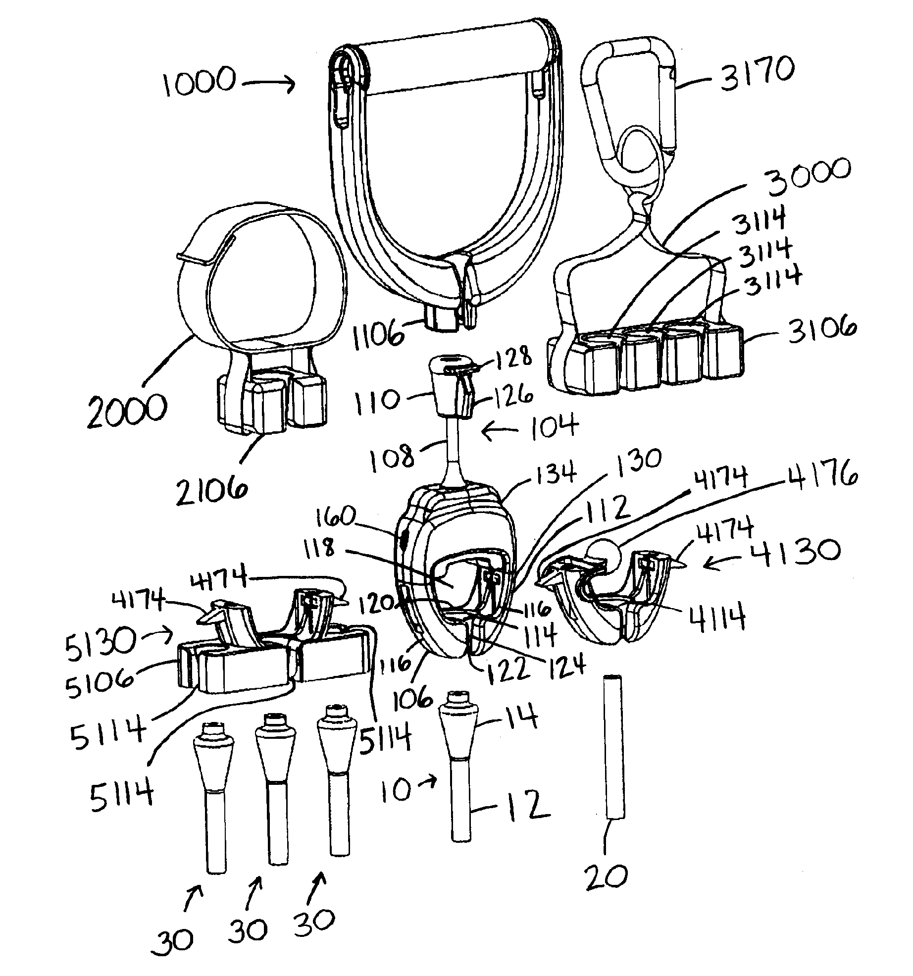
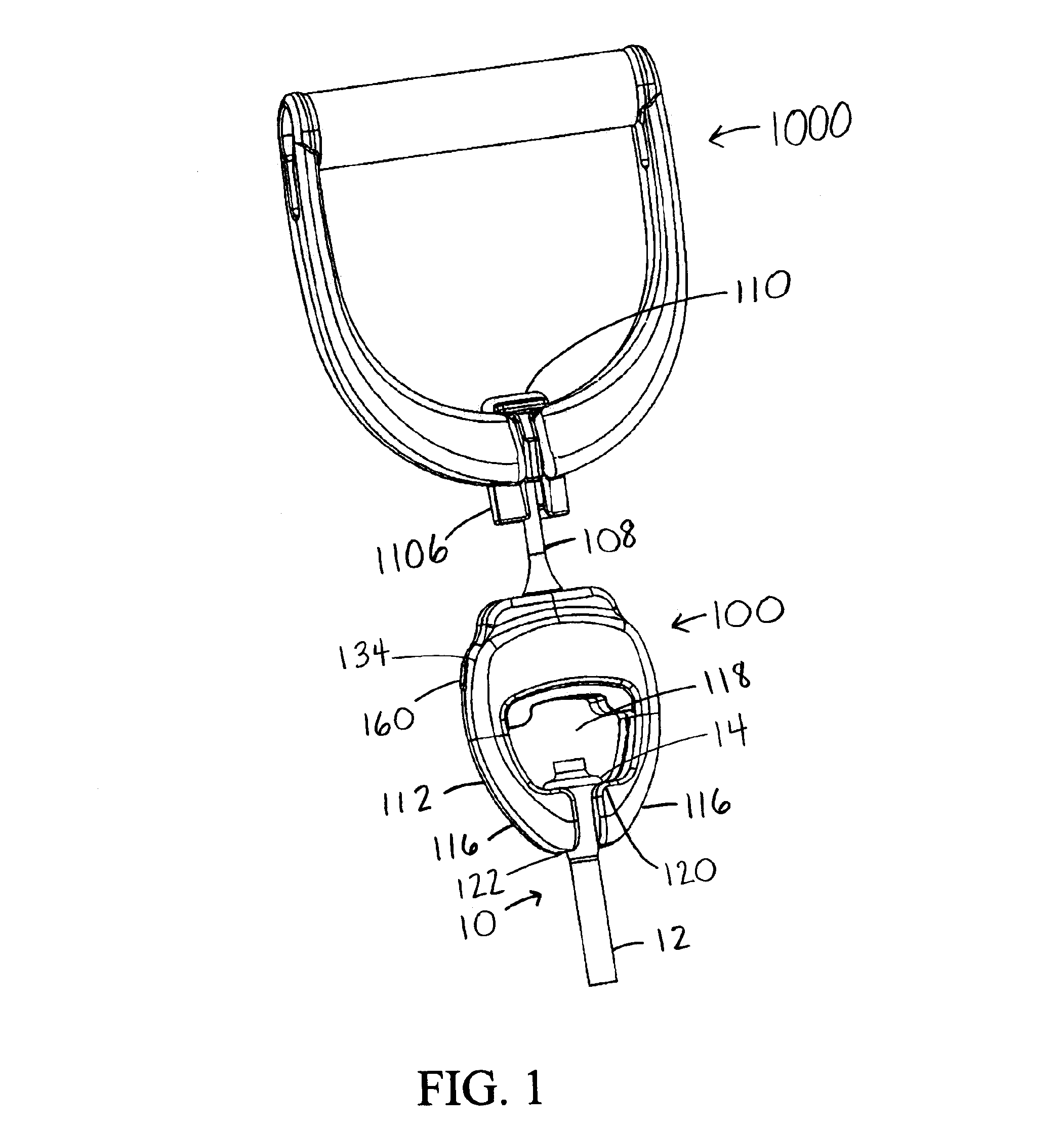
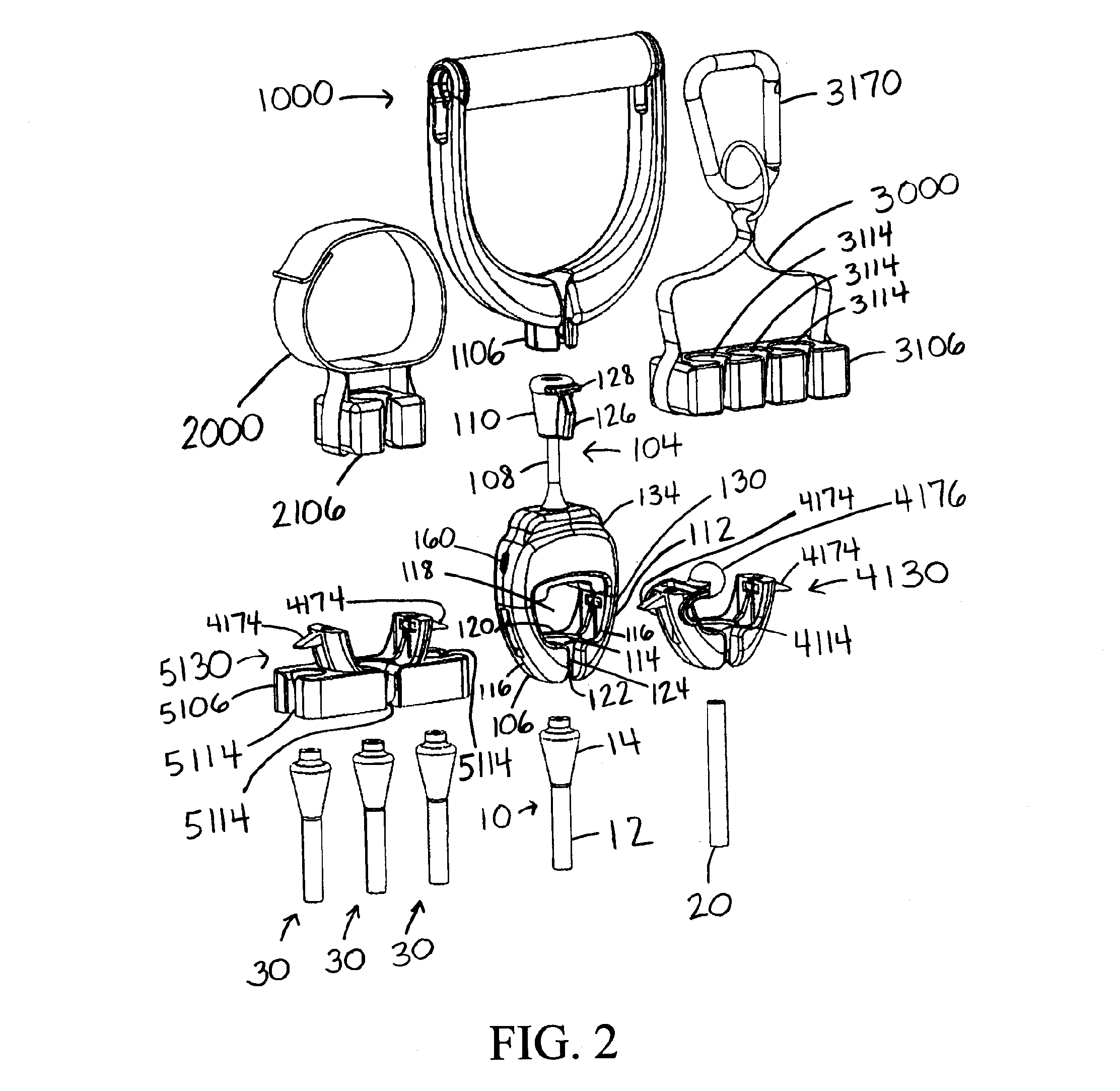
[0017]Expanding on the discussion above, FIG. 3 illustrates an exploded (disassembled) view of the sensor body 100 of FIGS. 1 and 2. The sensor body 100 includes a female connector section 130 having bars 132 extending upwardly from the socket body sides 116, with the ends of the bars 132 being sandwiched and pinned between the depicted halves 134A and 134B of a male connector section. These bars 132 each can bear a force sensor (a load cell) 102, such that tension (or compression) between the male connector section 134A / 134B and the female connector section 130—and thus on the bars 132 and the force sensors 102 thereon—results in a measurable signal representative of the force between the male and female connectors 104 and 106 of the sensor body 100.

[0018]The plug 110 and neck 108 of the male connector 104 are then shown in FIG. 3 between the halves 134A and 134B of the male connector section 134. The neck 108 is formed of a cable 136 terminating in crimped-on bosses 138 and 140, w...


PUM


Abstract

An exemplary exercise device includes a handheld force sensor with complementary male and female connectors extending from opposite sides thereof. The force sensor senses pulling and / or pushing forces exerted between the opposing sides. The male connector may be resistant to travel through the female connector except in limited orientations. The connectors allow the exercise device to interface with any mobile or immobile device having complementary connectors. Non-complementary connectors can connect with the exercise device through a body passage. Depending on devices interfaced with the exercise device, force readings can be taken during a vast variety of motions using different muscle groups during training, exercise, and rehabilitation / physical therapy in homes, schools, healthcare facilities, health clubs, etc. Force readings from the force sensor may be communicated via wired and / or wireless technologies to other devices for live (real-time) processing and display as well as additional historical analysis and reporting.

Description

CROSS-REFERENCE TO RELATED APPLICATIONS[0001]This application claims priority under 35 USC §119(e) to U.S. Provisional Patent Application 61 / 248,227 filed Oct. 2, 2009, the entirety of which is incorporated by reference herein.FIELD OF THE INVENTION[0002]This document concerns an invention relating generally to exercise devices, and more specifically to exercise devices having force sensors for measuring, recording, and / or providing feedback regarding a user's activity.BACKGROUND OF THE INVENTION[0003]Force sensors are sometimes incorporated into exercise devices for monitoring user activity, e.g., the amount of force applied, the duration of exercise, etc. The force sensors can allow a user (or others, e.g., trainers or physical therapists) to quantify, record, and analyze the user's activity with greater ease and certainty. For example, a sensor might precisely measure and record the amount of weight lifted during one exercise session, as well as the number of times it was lifted,...

Claims


Application Information

Patent Timeline
Patent Type & Authority Patents(United States)
IPC IPC(8): A63B24/00
CPCA61B5/224A63B21/0552A63B21/1434A63B21/1442A63B21/1469A63B24/0062A61B5/0002A63B21/0557A63B2021/0055A63B2071/0625A63B2071/0627A63B2071/063A63B2071/0655A63B2220/51A63B2225/20A63B2225/50A63B2230/06A63B2230/75A63B21/4035A63B21/4017A63B21/4021A63B21/0055
Inventor HINDS, ROBERT S.BRAIER, ROBERT A.STEPHENSON, JOHN
Owner KIIO
Why Eureka
Try Eureka