
System and method to automatically configure an aircraft for an operational flight phase

Active Publication Date: 2013-07-23
ROCKWELL COLLINS INC
View PDF7 Cites 24 Cited by
  • Summary
  • Abstract
  • Description
  • Claims
  • Application Information

AI Technical Summary

Benefits of technology

The present invention is a system that automates the process of configuring an aircraft for operational flight, reducing the time required for setup and the likelihood of errors. This is achieved through pre-determined configuration settings and a closed-loop checklist, which also reduces the amount of time needed to verify the configuration. Overall, this system improves operational efficiency and safety.

Problems solved by technology

For example, on-board data load is disabled when the aircraft is in-air.
Such methods are not able to account for all the real-time conditions that affect flight phase determination and they are not able to account for the operational intent of the pilot.
In addition, current implementations are often federated, meaning each function uses its own inputs and logic, which can lead to flight phase disagreement between systems.
The limitations of the current methods will be a hindrance to the introduction of new flight deck automation, which have increased dependency on the unambiguous and consistent determination of the operational flight phase.
Such systems may define modes such as “altitude hold” or “lateral navigation”, however, these modes refer to the mode of the flight management or autopilot system, not the operational intent of the pilot.
Such methods are not able to account for all the real-time conditions that affect flight phase determination.
In addition, current implementations are often federated, meaning each function uses its own inputs and logic, which can lead to mode disagreement between systems.
A deficiency in today's avionics systems is that the system modes as defined by the current state of the art do not take into account the operational flight phase and do not modify their operation based on the operational flight phase.
This places a burden on the pilot to understand the objectives of the intended operational flight phase and configure the aircraft systems appropriately.
This imposes additional workload on the pilot and in some cases has led to accidents such as unintentional aircraft movement during return-to-service engine checks.
Additionally, the prior art does not address the effect of the higher level operational flight phases on the on-board systems and the high workload placed on the pilot to properly configure the on-board systems appropriately for the intended operation.
Depending on the amount of automation available on the airplane, the length of the checklist, the number of items that must be configured, checked, and cross-checked can cause a significant amount of heads down time and an opportunity for errors.
The lengthy heads down time contributes to workload and time away from the primary tasks of “aviate, navigate, and communicate”.
Configuration errors can lead to subsequent higher downstream workload to correct the problem, or, in the worst case, unsafe operating conditions

Method used


Image

  • System and method to automatically configure an aircraft for an operational flight phase
  • System and method to automatically configure an aircraft for an operational flight phase
  • System and method to automatically configure an aircraft for an operational flight phase

Examples


Embodiment Construction

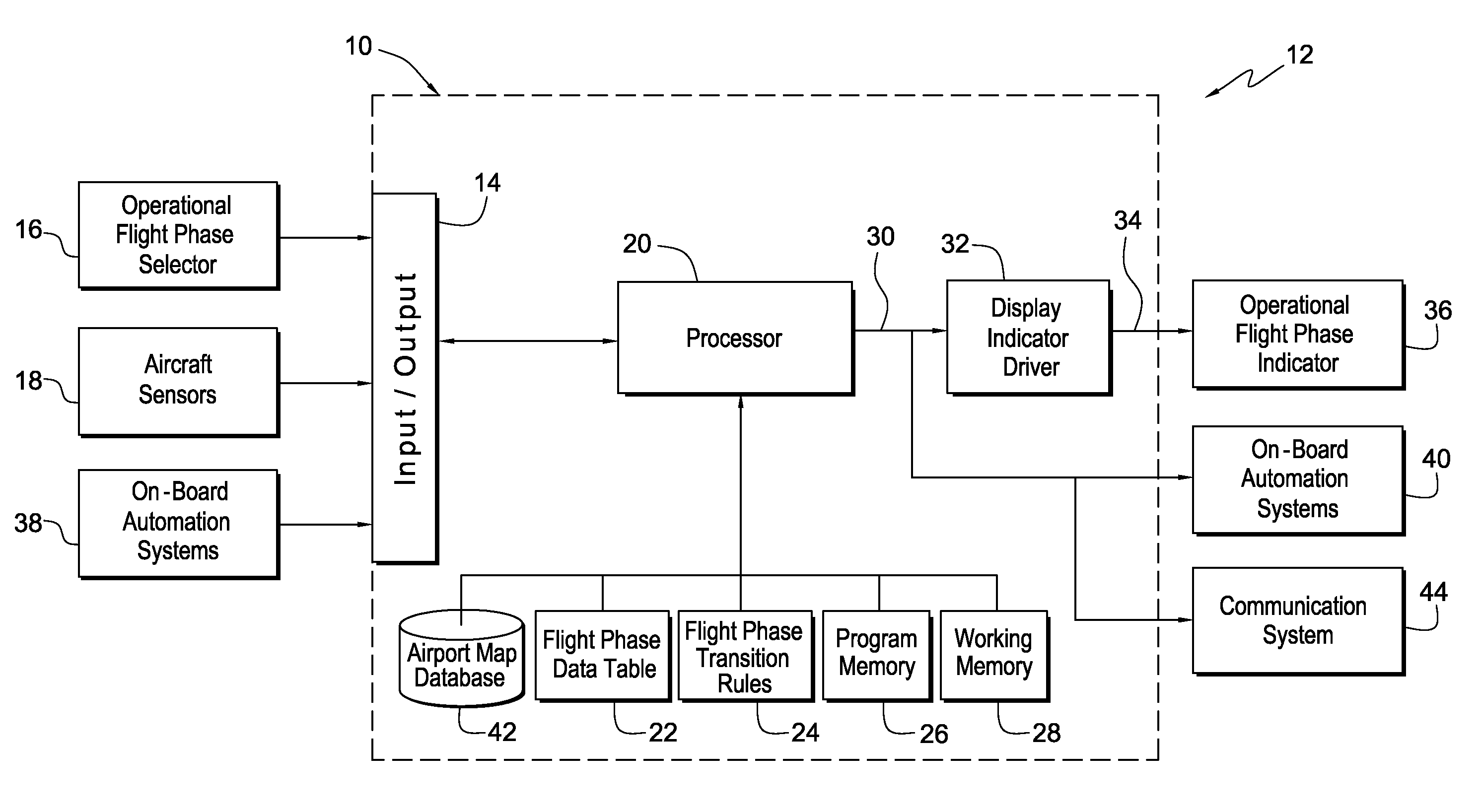
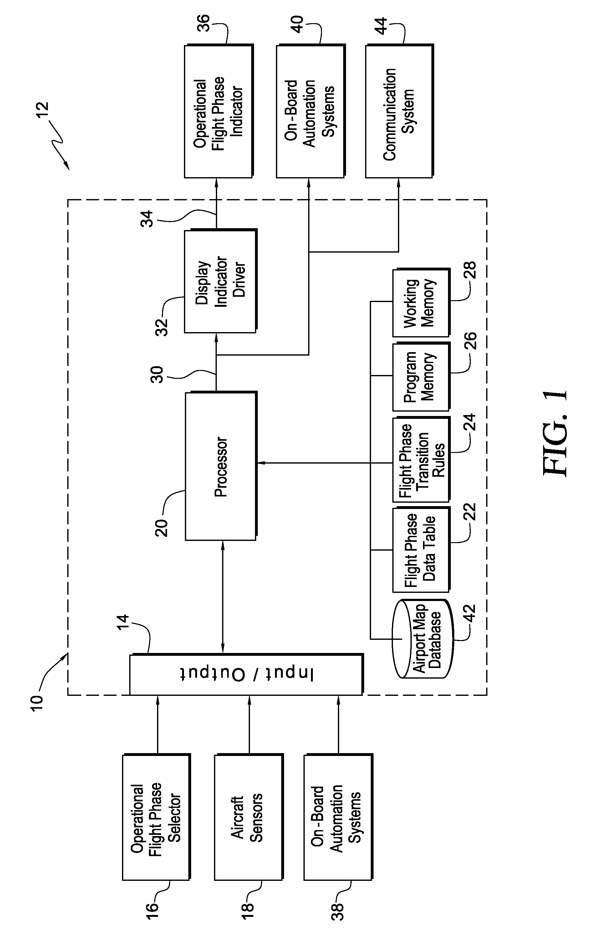
[0031]Referring now to the drawings and the characters of reference marked thereon, FIG. 1 illustrates a preferred embodiment of the operational flight phase determination and indication system of the present invention, designated generally as 10, in an aircraft environment, designated generally as 12. The operational flight phase determination and indication system 10 includes input / output circuitry 14 for receiving an operational flight phase selector output signal from an operational flight phase selector 16 and aircraft sensor signals from aircraft sensors 18. A processor 20 is coupled to the input / output circuitry 14. A flight phase data table 22 is coupled to the processor 20. The flight phase data table 22 includes a list of the defined operational flight phases for the aircraft. A flight phase transition rules set 24 is coupled to the processor 20. The flight phase transition rules set 24 includes flight rules for defining flight phase transitions. Program memory 26 and work...


PUM


Abstract

An operational flight phase determination, indication and configuration system for an aircraft includes input / output circuitry for receiving an operational flight phase selector output signal, aircraft sensor signals, and on-board automation system output signals including configuration status information. A processor is coupled to the input / output circuitry. A flight phase data table is coupled to the processor. The flight phase data table includes a list of the defined operational flight phases for the aircraft. A flight phase transition rules set is coupled to the processor. The flight phase transition rules set includes flight rules for defining flight phase transitions. An aircraft system configuration data table is coupled to the processor. The aircraft system configuration data table includes a list of the defined configurations for each operational flight phase and the aircraft system configuration settings for each configuration. Program memory and working memory are coupled to the processor. The processor uses input from the input / output circuitry, the flight phase data table, the flight phase transition rules set, the program memory, the working memory, and the aircraft system configuration data table to provide an operational mode signal indicating the operational mode of the aircraft and a configuration command signal. A display indicator driver is coupled to the processor for providing display indicator driver signals to an operational flight phase indicator in accordance with the operational mode signal. Output drivers are coupled to the processor for providing configuration commands to aircraft systems in accordance with the configuration command signal.

Description

CROSS REFERENCE TO RELATED APPLICATIONS[0001]This is a continuation-in-part of U.S. Ser. No. 12 / 504,524, entitled “Operational Flight Phase Determination and Indication System”, filed Jul. 16, 2009.BACKGROUND OF THE INVENTION[0002]1. Field of the Invention[0003]The present invention relates generally to systems for providing operational flight phase indications, configuring aircraft systems, and more particularly to a system for determining and indicating operational flight phase, and configuring the aircraft systems according to the operational flight phase utilizing aircraft sensors, airplane automation modes, operational flight phase data tables, aircraft systems configuration data tables and flight crew input.[0004]2. Description of the Related Art[0005]Some avionics functions are dependent on the aircraft's phase of flight. For example, on-board data load is disabled when the aircraft is in-air. A slightly more complex example is the on-board weather radar, which uses a variety...

Claims


Application Information

Patent Timeline
IPC IPC(8): G01C21/00
CPCG08G5/0021G05D1/101G08G5/0047G01R31/008
Inventor CARRICO, MATTHEW J.
Owner ROCKWELL COLLINS INC
Learn More