Hydraulic system

a technology of hydraulic system and valve body, which is applied in the direction of fluid coupling, positive displacement liquid engine, servomotor, etc., can solve the problems of high losses in lines and valves, and achieve the effects of low drive rotational speed, reduced power loss, and large volume flow

Active Publication Date: 2013-07-30
DEERE & CO
View PDF3 Cites 5 Cited by
  • Summary
  • Abstract
  • Description
  • Claims
  • Application Information

AI Technical Summary

Benefits of technology

[0011]When a predetermined drive rotational speed value is exceeded the control pressure difference of the adjustable pump can be reduced. Here the predetermined drive rotational speed that triggers the readjustment of the control pressure difference can be provided as input depending on the application preferably over an input module on an operator's display of an operating implement or over another appropriate input interface of the control unit. However, depending on the magnitude of the power of the adjustable pump, a fixed drive rotational speed can be provided and stored in memory in the control unit.
[0017]The hydraulic system, according to the invention, permits optimum operation of a hydraulic system in all operating conditions for the drive of the vehicle and is used in particular to reduce power losses and to make available large volume flows at low drive rotational speed. If necessary, very large conveyed volume flows are possible despite small line cross sections and valves. It is thereby possible to retain the existing valves and lines without the need for a larger adjustable pump. Moreover, in the case of failure of the electrical system assurance can be provided despite electronic control of the conveyed volume flow electronic controller that the existing hydraulic system continues to be available.

Problems solved by technology

The adjustable pump, however, on the basis of its maximum conveyed volume flow, has the possibility of conveying conveyed volume flows of Vmax 1 / min that would result in high losses in the lines and the valves.

Method used


Image

  • Hydraulic system
  • Hydraulic system
  • Hydraulic system

Examples


Embodiment Construction

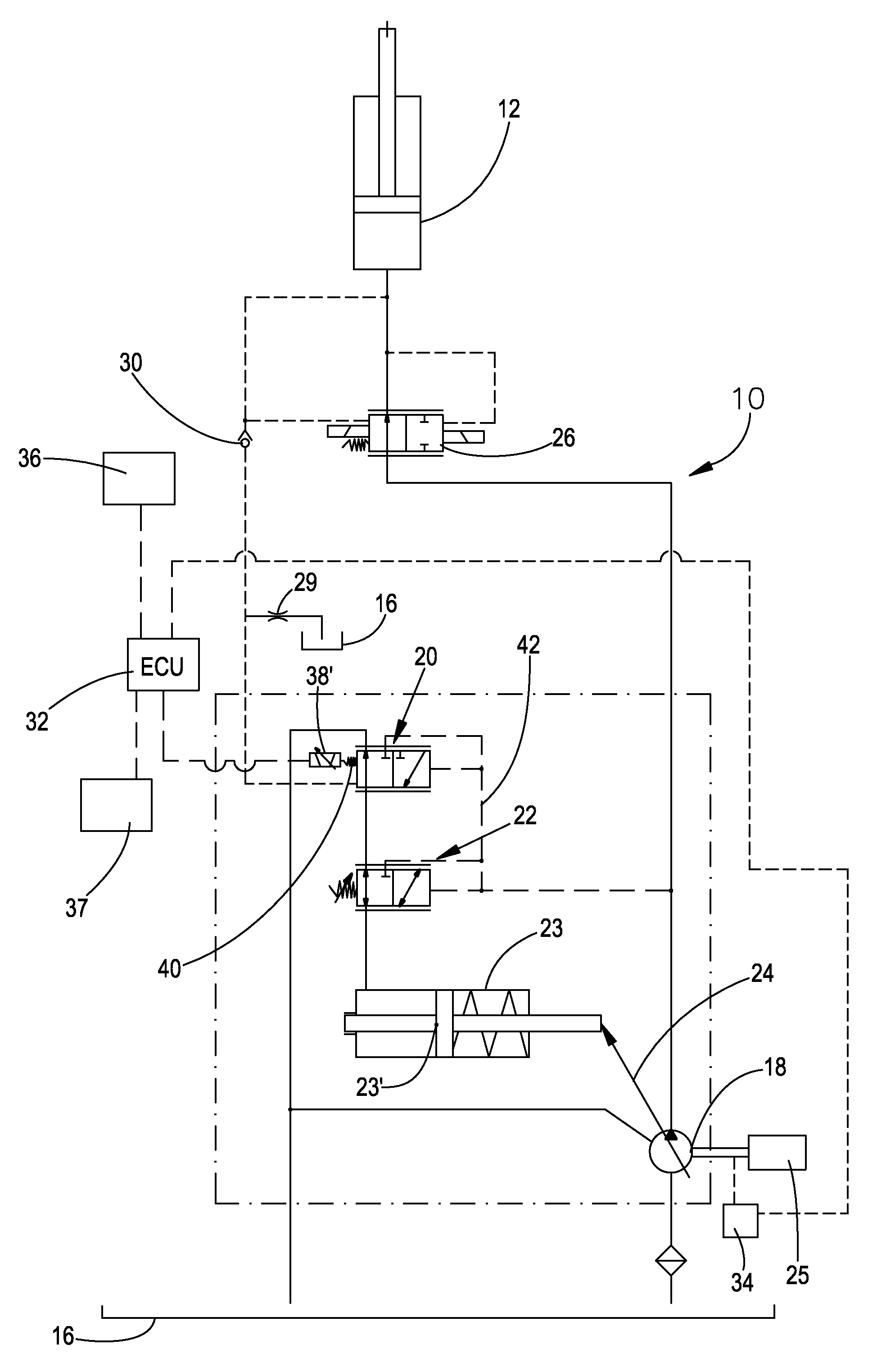
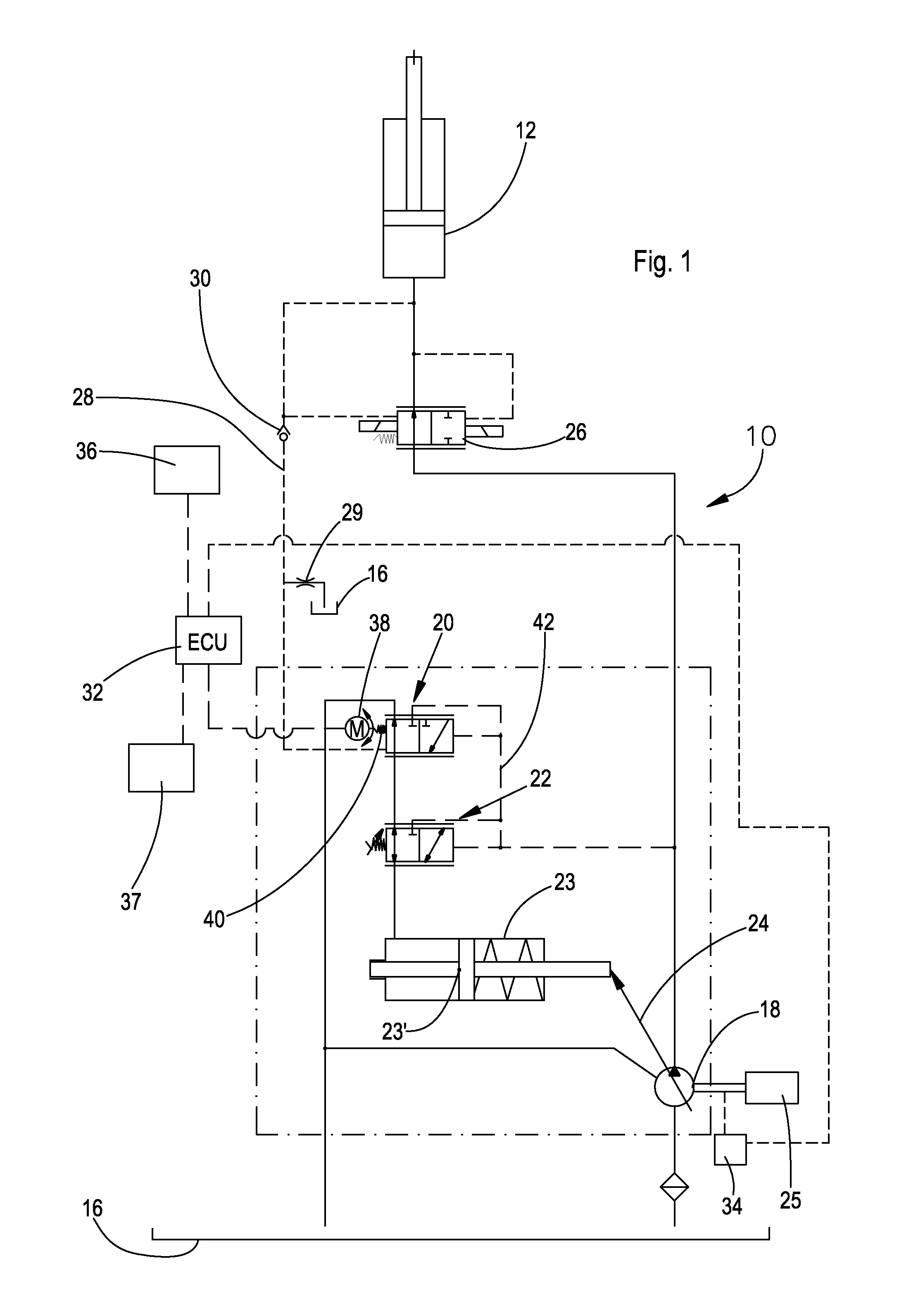
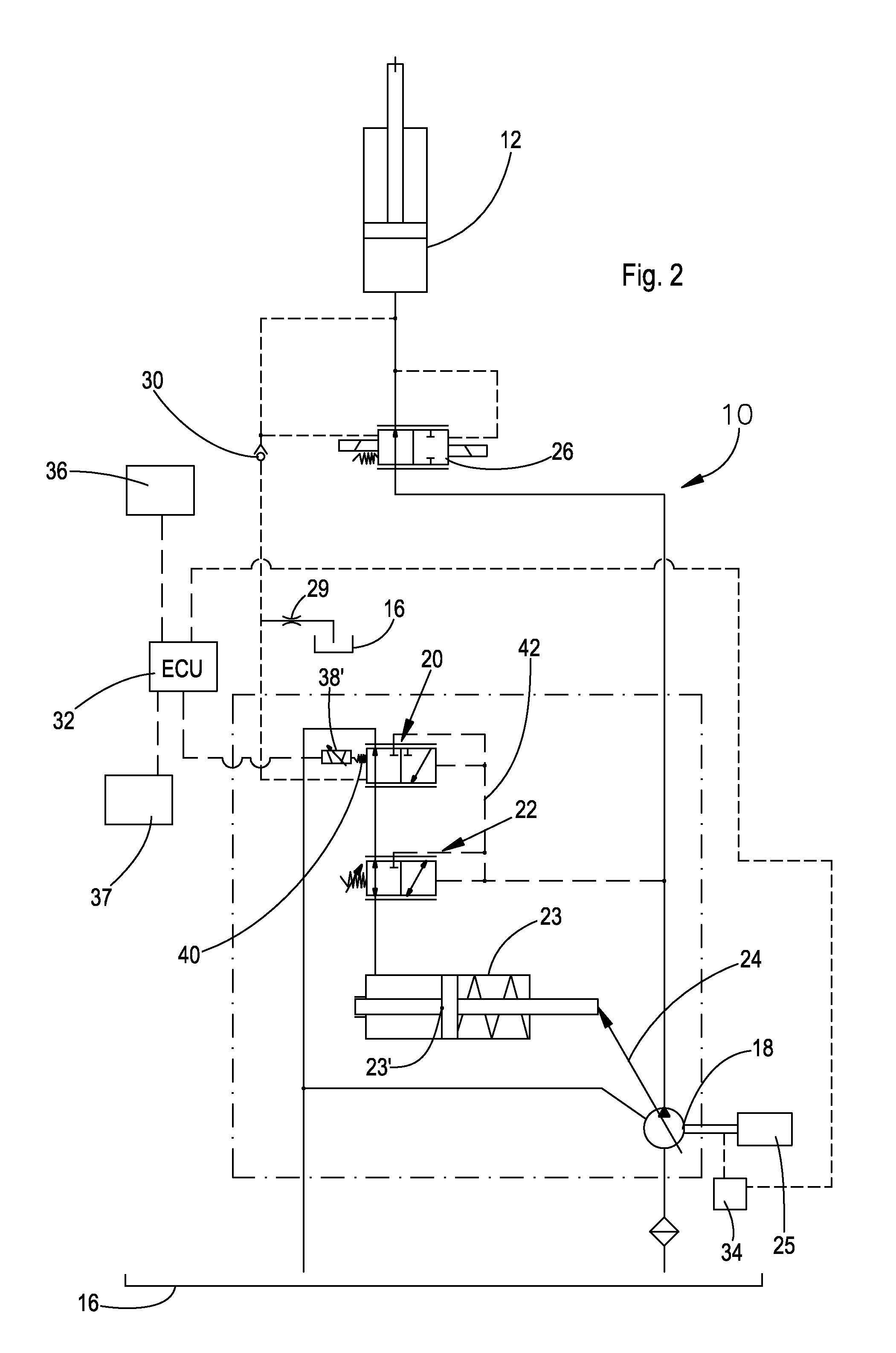
[0021]Referring to FIG. 1, a hydraulic system 10 operates a hydraulic consumer 12, for example, a hydraulic cylinder for raising and lowering a front loader 14. The hydraulic system 10 includes a hydraulic reservoir 16, an adjustable hydraulic pump 18 with a conveyed volume flow controller 20 for controlling a pressure difference between adjustable pump 18 and the consumer 12, a pressure limiter 22 to limit the operating pressure for the adjustable pump 18, as well as an adjustable piston 23 for the adjustment and limitation of the conveyed volume flow of the adjustable pump 18, that can be adjusted by a conveyed volume flow adjusting arrangement 24. Moreover, a stop 23 or an adjustable spindle, is provided for the adjustable piston 23, that can be brought into engagement with the adjustable piston 23 and with which a maximal conveyed volume flow of the adjustable pump 18 can be adjusted. The adjustable pump 18 is driven by an internal combustion engine 25. A hydraulic control valve...


PUM


Abstract

A hydraulic system includes an engine driven adjustable hydraulic pump which supplies fluid to a hydraulic consumer, and an electronic control unit. The adjustable pump includes flow controller for controlling a pressure difference between the consumer and the adjustable pump to a pre-determined control pressure difference. The flow controller includes an actuator controlled by the control unit, through which the pressure difference can be controlled. The electronic control unit receives an engine speed signal and controls the actuator to control the pressure difference, in order to make power delivery of the adjustable pump conform to the operating conditions of a vehicle.

Description

FIELD OF THE INVENTION[0001]The present invention relates to a hydraulic system for an engine driven vehicle.BACKGROUND OF THE INVENTION[0002]Agricultural machines such as tractors, construction machines loaders or other types of operating machines, typically have a hydraulic system with which one or more hydraulic consumers such as hydraulic cylinders, hydraulic motors or other hydraulically driven components. Such hydraulic systems include hydraulic pumps that can be connected directly or over a connecting gearbox with fast or slow fixed gear ratios to the drive shaft of a drive engine. Thereby the maximum volume flow that can be conveyed by the hydraulic pump varies with the rotational speed of the drive engine. The faster the rotational speed of the drive engine the larger is the volume flow that can be conveyed by the hydraulic pump. In adjustable load-sensed controlled hydraulic pumps, so called adjustable pumps, as they are being applied today in the state of the art, the max...

Claims


Application Information

Patent Timeline
Patent Type & Authority Patents(United States)
IPC IPC(8): F15B11/02F04B49/00
CPCE02F9/2235E02F9/2296F04B49/06F04B49/10F15B11/0423F15B2211/20553F15B2211/633F15B2211/6343F15B2211/6652F15B2211/253F15B2211/6653
Inventor BITTER, MARCUS
Owner DEERE & CO
Why Eureka
Try Eureka