Convertible vehicle storage rack

a technology for vehicles and roof racks, applied in the field of vehicle storage racks, can solve the problems of difficult and/or dangerous removal and replacement by a single individual, cumbersome and difficult tasks, and heavy roof racks

Active Publication Date: 2013-07-30
INTELLIGENT DESIGNS 2000
View PDF66 Cites 49 Cited by
  • Summary
  • Abstract
  • Description
  • Claims
  • Application Information

AI Technical Summary

Benefits of technology

[0006]It is one aspect of embodiments of the present invention to provide a roof storage rack (“roof rack”) for installation on a vehicle. The roof rack of one embodiment of the present invention includes a light bar for accommodating at least one light that is interconnected to the vehicle adjacent to the windshield and selectively interconnected to the roof rack. The roof rack of this embodiment of the present invention is also interconnected to a support bar that is rotatably interconnected to members that are associated with a rear portion of the vehicle. One advantage of embodiments of the present invention is that the roof rack is installed by using existing holes and / or standard hardware of the vehicle so that no modifications need to be made to the vehicle.
[0007]It is another aspect of one embodiment of the present invention to provide a roof rack that includes a light bar that remains interconnected to the vehicle when the roof rack is moved therefrom. More specifically, one embodiment of the present invention employs a light bar that is firmly associated with a windshield frame of a vehicle. As one skilled in the art will appreciate, often the lights associated with a light bar, such as fog lights, include a plurality of wires that are interconnected to the power source of the vehicle. These wires are often fed through the tubular structure of the light bar and interconnected to the battery of the vehicle. In one embodiment of the present invention, the light bar remains fixed to the vehicle roof and / or windshield frame such that removal of the remainder of the roof rack from the roof does not require disconnection of the lights.
[0008]It is another aspect of one embodiment of the present invention to provide a roof rack that is relatively easy to install. More specifically, one advantage of embodiments of the present invention is that no additional holes need to be drilled into the vehicle for installation. That is, embodiments of the present invention utilize holes and / or fasteners of the vehicle frame and / or body. Further, one embodiment of the present invention uses both the vehicle frame and body to provide a stable roof rack that helps prevent roof rack sway. A plurality of wear plates may be glued or otherwise interconnected to the vehicle to prevent vehicle marring or wear from portions of the roof rack that are positioned adjacent to the vehicle body. As such, the roof rack may be easily installed and removed without damaging the vehicle, which improves the potential resale value thereof.
[0009]It is another aspect of one embodiment of the present invention to provide a roof rack that may be installed and operated by a single individual. More specifically, the roof rack may be disassembled into easy to handle pieces that facilitate integration onto the vehicle. In operation, the roof rack is designed to rotate away from the roof and the light bar and then be supported by a lanyard, rope, tether or bungee that interconnects the roof rack to the light bar. Roof racks of embodiments of the present invention are thus able to achieve the contemplated rotation under the force and guidance of one individual, which will be described in further detail below.

Problems solved by technology

Storage racks are often installed on vehicles to permit carrying additional items that will not fit within the vehicle or are not desirable to carry in the vehicle.
It is sometimes necessary to remove the storage rack to make modifications to the vehicle.
This is often a cumbersome and difficult task wherein the aforementioned lights and associated wiring must be removed.
To complicate this task, roof racks are often heavy, and may be difficult and / or dangerous to remove and replace by a lone individual.
Another drawback of the roof racks of the prior art is that they are often hard-mounted to the vehicle, which requires the drilling of additional holes into the vehicle.
If drilled by the end user, these holes are often located incorrectly, thereby requiring re-drilling, and possibly, decreasing the resale value of the vehicle.

Method used


Image

  • Convertible vehicle storage rack
  • Convertible vehicle storage rack
  • Convertible vehicle storage rack

Examples


Embodiment Construction

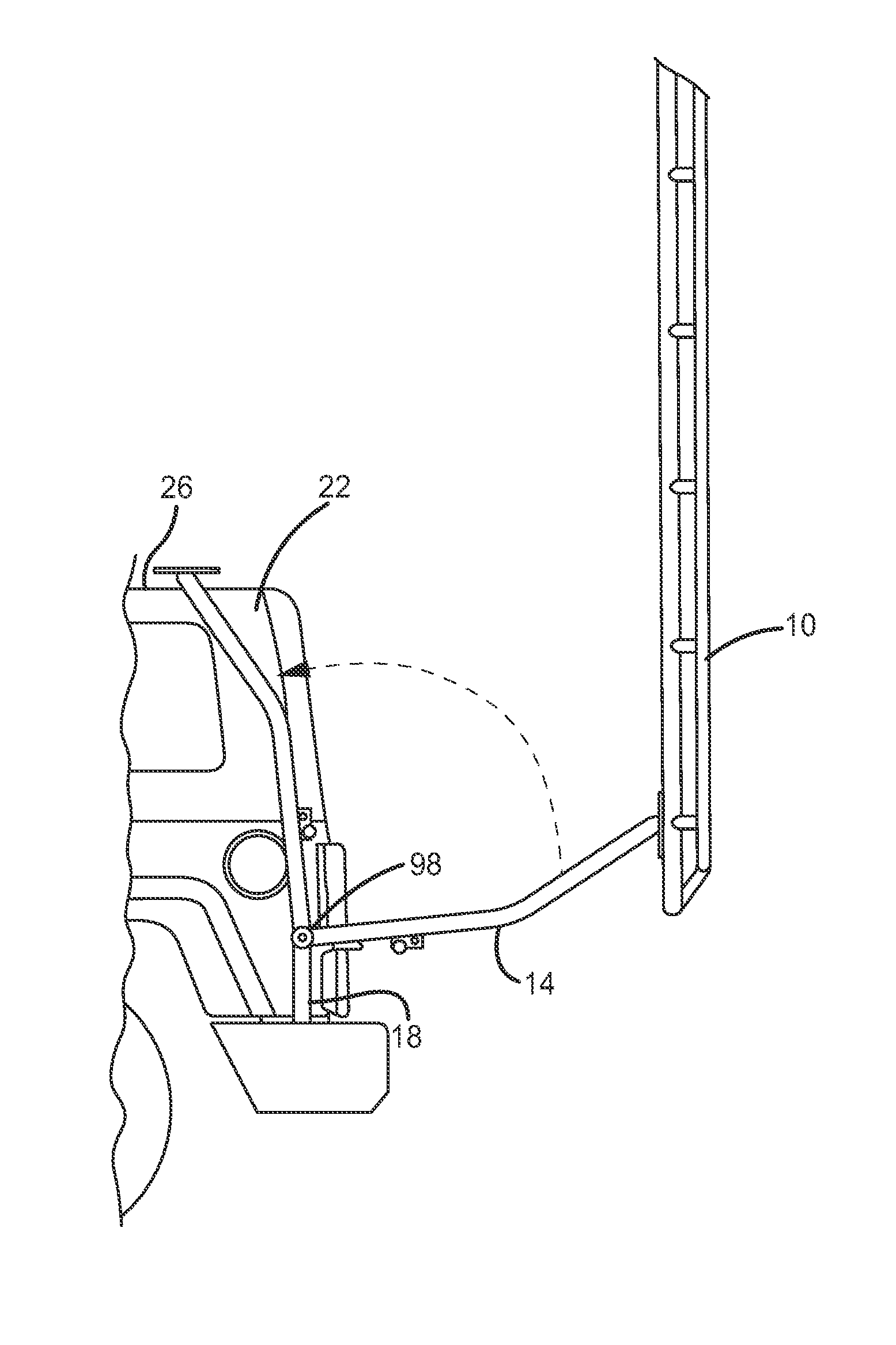
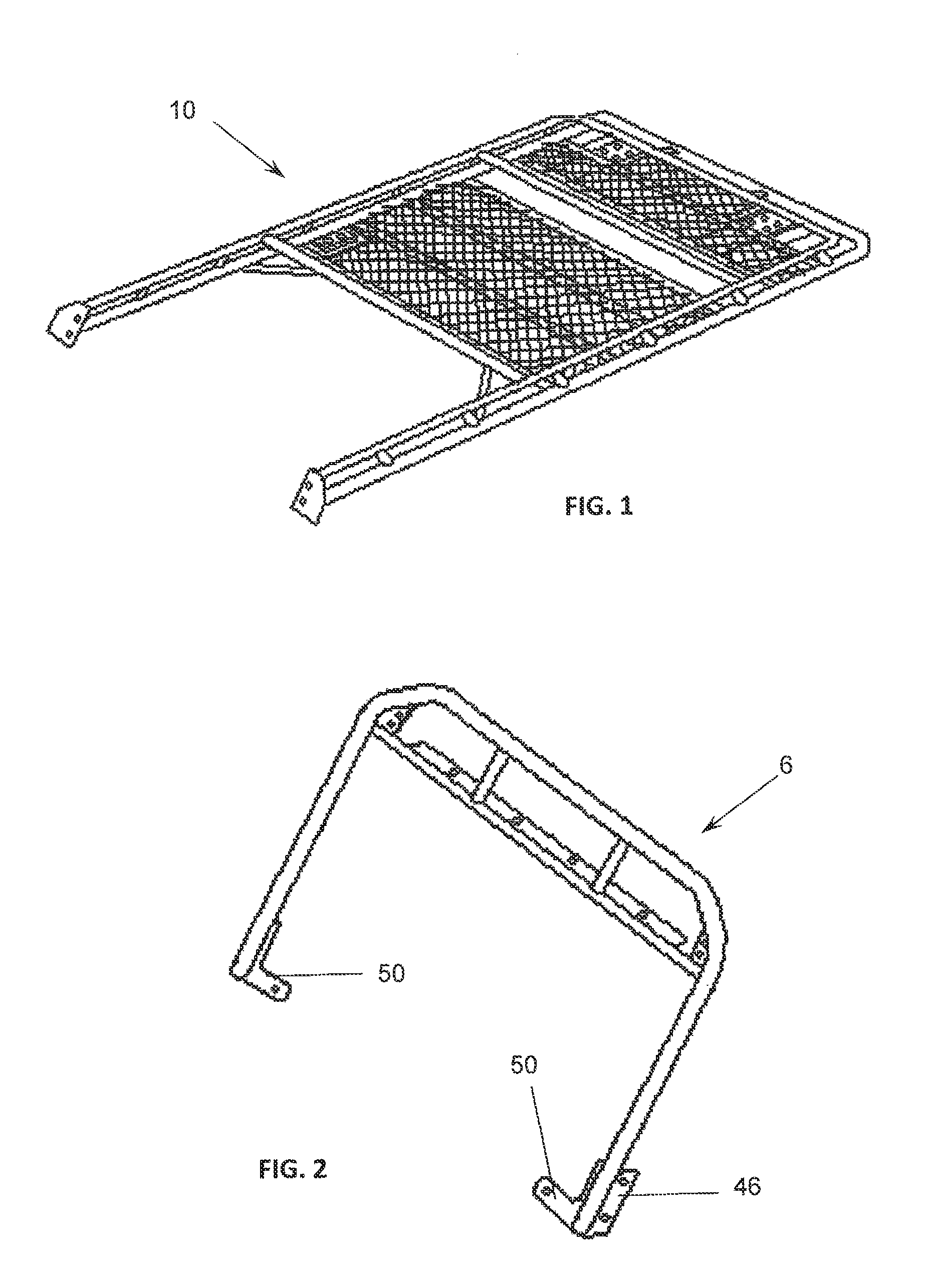
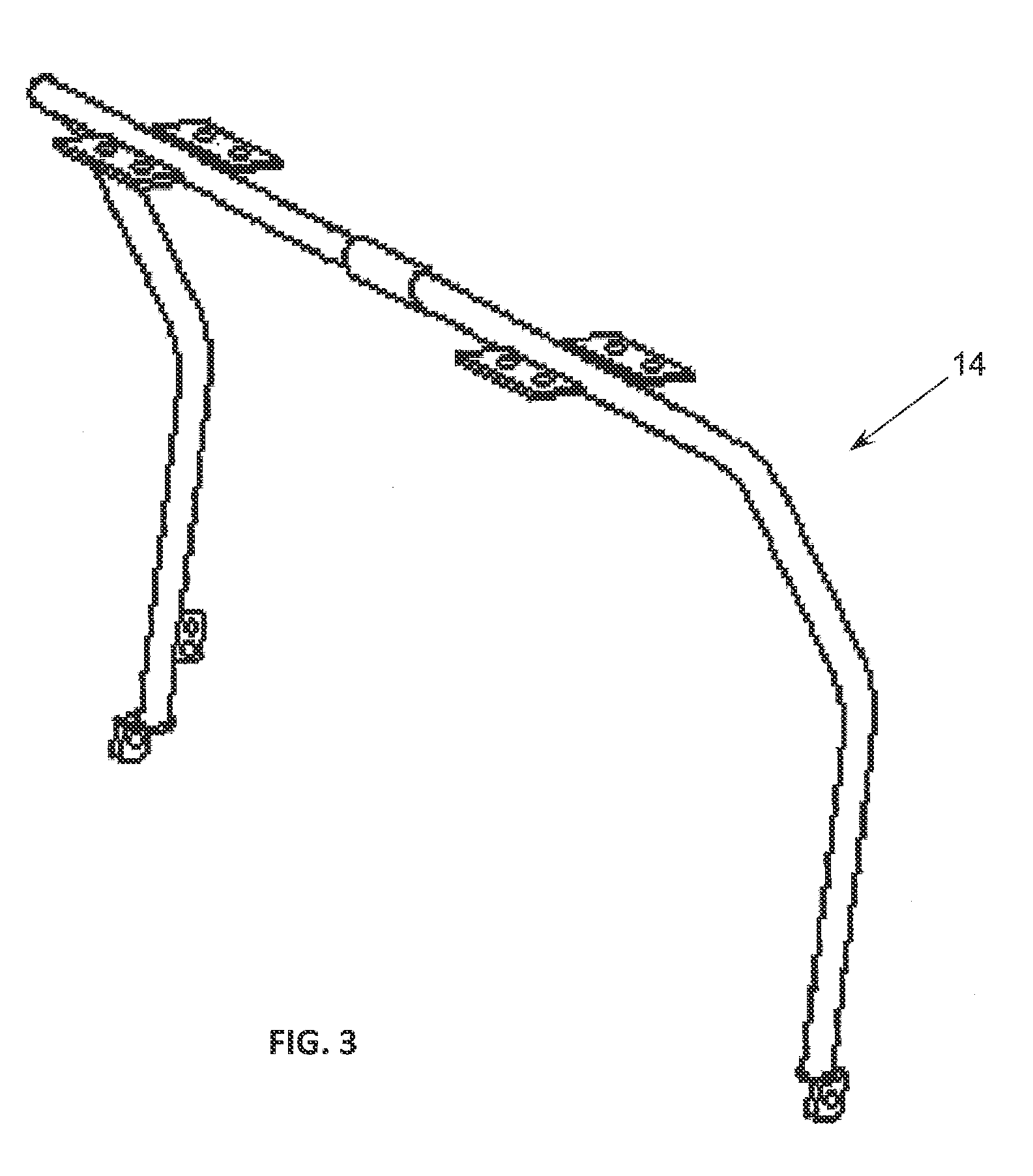
[0051]Referring now to FIGS. 1-19, a convertible roof rack system 2 of one embodiment of the present invention is shown. More specifically, the convertible roof rack system 2 is comprised of a light bar 6, a roof rack 10, a support bar 14, and support towers 18 that are all operably interconnected to a vehicle 22. The roof rack 10 is placed above the roof 26 of the vehicle 22 and adjacent to a rear end and windshield 30 thereof. The support bars 14 are rotatably interconnected to the support towers 18 and are thus able to move from a first position of use adjacent to the roof 26 to a second position of use away from the vehicle 22. A front end of the roof rack 10 is selectively interconnected to the light bar 6, which is firmly interconnected on the windshield frame 34 adjacent to the windshield 30 of the vehicle 22. Thus, the roof rack 10 may be rotated away from the roof 26 of the vehicle 22 while the light bar 6 remains in place.

[0052]Referring now to FIGS. 2, 6, 7, and 20-23 the...


PUM

PropertyMeasurementUnit
movementaaaaaaaaaa
areasaaaaaaaaaa
structureaaaaaaaaaa

Abstract

A convertible roof rack is provided that is generally comprised of a light bar and a roof rack that is spaced from the roof of a vehicle. The roof rack is also rotatably interconnected to a support structure associated with the rear of the vehicle such that it is capable of moving from a first position of use adjacent to the roof to a second position of use away from the roof where the light bar remains interconnected to the vehicle adjacent to the windshield. As such, electrical connections associated with the light bar remain intact when the roof rack is rotated away from the roof.

Description

CROSS REFERENCE TO RELATED APPLICATIONS[0001]This patent application claims the benefit of U.S. Ser. No. 61 / 237,177, filed Aug. 26, 2009, entitled “Convertible Vehicle Storage Rack”, which is incorporated by reference in its entirety herein. This application is also related to U.S. Patent Application Publication No. 2005 / 0082326, filed Sep. 24, 2004, entitled “Multi-Purpose Storage Rack for a Sport Utility Vehicle”, U.S. Pat. No. D578,952, filed Feb. 20, 2008, entitled “Sport Utility Vehicle Rack”, U.S. Pat. No. D512,783, filed Jun. 4, 2003, entitled “Vehicle Ladder”, and U.S. Pat. No. D508,015, filed Mar. 17, 2003, entitled “Multi-purpose Storage Rack for a Sport Utility Vehicle”, the entire disclosures of which are incorporated by reference herein.FIELD OF THE INVENTION[0002]Embodiments of the present invention are generally related to storage racks for interconnection to a motor vehicle. More specifically, one embodiment of the present invention is a vehicle storage rack with lig...

Claims


Application Information

Patent Timeline
Patent Type & Authority Patents(United States)
IPC IPC(8): B60R9/045B60R9/04
CPCB60R9/045Y10T29/49716B60R3/005B60R9/0423
Inventor BADILLO, PAUL
Owner INTELLIGENT DESIGNS 2000
Why Eureka
Try Eureka