Aortic valve replacement

a technology for aortic valves and valves, applied in the field of aortic valve replacement, can solve the problems of bioprosthetic valves, low patient life, and low durability compared to mechanical valves, and achieve the effects of improving patient life, high morbidity and mortality rates, and reducing durability

Inactive Publication Date: 2013-07-30
EDRICH HEALTH TECH
View PDF4 Cites 19 Cited by
  • Summary
  • Abstract
  • Description
  • Claims
  • Application Information

AI Technical Summary

Problems solved by technology

Bioprosthetic valves, however, have diminished durability compared to mechanical valves and frequently fail during the patient's lifetime because of stenosis due to leaflet fusion and or calcification, or incompetence due to leaflet tears and degeneration.
Subsequent surgical intervention to replace these failed valves is associated with very high morbidity and mortality rates because of the generally poor medical condition of the subjects.
Attempts to hold these new valves in place using stents have not provided durable results for obvious reasons.

Method used


Image

  • Aortic valve replacement
  • Aortic valve replacement
  • Aortic valve replacement

Examples


Embodiment Construction

[0043]In the following is described the preferred embodiments of the present invention. In describing the embodiments illustrated in the drawings, specific terminology will be used for the sake of clarity. However, the invention is not intended to be limited to the specific terms so selected, and it is to be understood that each specific term includes all technical equivalents that operate in a similar manner to accomplish a similar purpose.

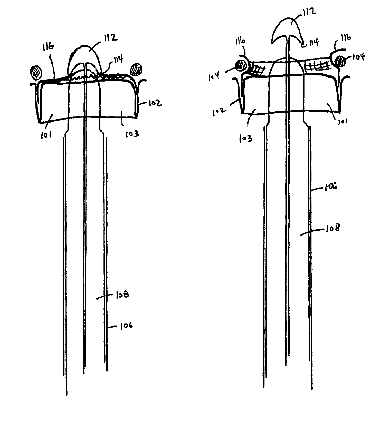
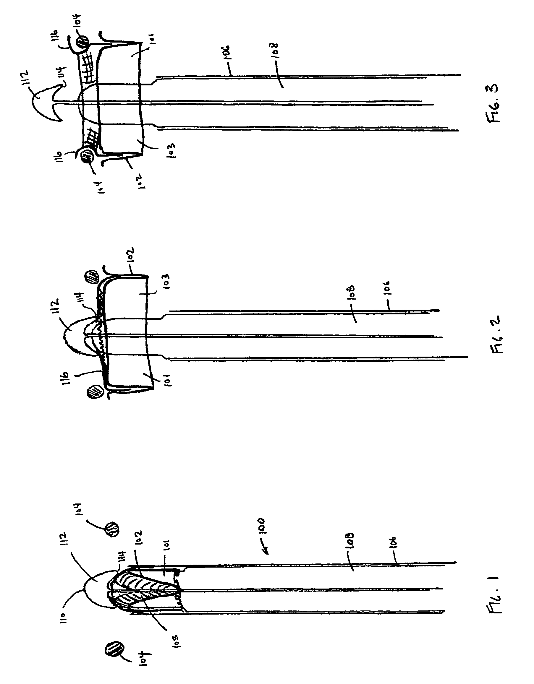
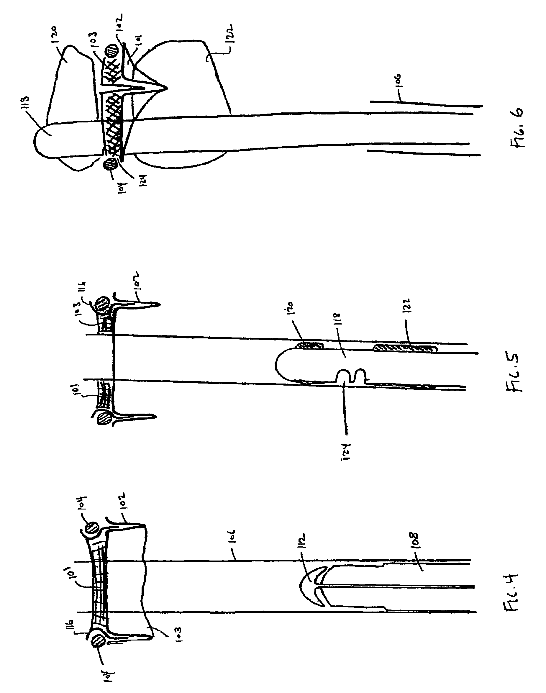
[0044]One aspect of the present invention concerns the replacement of a bioprosthetic aortic valve using a minimally invasive transvascular approach. In order to provide such a replacement, the leaflets of the prior bioprosthetic valve may be destroyed and pushed aside using for example, an appropriately sized non compliant balloon. Once the area is cleared, a valve 101 supported on a memory metal frame 102 sized to fit into the annulus 104 of the prior bioprosthetic valve may be delivered to the site using standard catheter techniques.

[0045]It i...


PUM


Abstract

A device for replacement of a bioprosthetic valve having an annulus (104) and one or more leaflets (105), the device having an outer housing (106) and an inner shaft (108) with a distal end (110). The outer housing (106) is slideable relative to the inner shaft (108) such that a portion of the inner shaft (108) may be revealed. A cap (112) is associated with the distal end (110) of the inner shaft (108), the cap (112) movable between a first position adjacent the inner shaft (108) and a second position displaced from the inner shaft (108). The cap (112) is adapted to trap a skirted valve frame (102) between said cap (112) and the inner shaft (108) when in the first position. The skirted valve frame (102) may be released by the cap (112) upon sliding of the outer housing (106) relative to the inner shaft (108) to reveal the inner shaft (108) and upon movement of the cap (112) to the second position. Also disclosed are associated methods.

Description

CROSS REFERENCE TO RELATED PATENT APPLICATION[0001]The present application claims the benefit of the filing date of U.S. Provisional Patent Application No. 60 / 784,892 filed Mar. 23, 2006, the disclosure of which is hereby incorporated herein by reference.BACKGROUND OF THE INVENTION[0002]Previous patent applications by the inventors herein, including U.S. application Ser. Nos. 10 / 737,466 and 10 / 837,827, and related applications, which are all incorporated by reference herein in their entireties, disclose and relate to a stapling device for use in the fixation of endovascular grafts to the walls of vessels. The present disclosure builds on those teachings by providing, in accordance with certain aspects, novel valve structures and surgical instruments for replacing a failing bioprosthetic aortic valve using a minimally invasive transvascular approach. The present disclosure also discloses methods for replacing a failing bioprosthetic aortic valve using a minimally invasive approach. T...

Claims


Application Information

Patent Timeline
Patent Type & Authority Patents(United States)
IPC IPC(8): A61F2/24
CPCA61F2/2412A61F2/2436
Inventor EDOGA, JOHN K.RICHARD, THIERRY
Owner EDRICH HEALTH TECH
Why Eureka
Try Eureka