Method for reducing power requirements in active load pull system
What is Al technical title?
Al technical title is built by PatSnap Al team. It summarizes the technical point description of the patent document.
a load pull system and power requirement technology, applied in the direction of resistance/reactance/impedence, instruments, measurement devices, etc., can solve the problems of limited tuning range of passive impedance tuners and the reduction of the available tuning range at the dut reference plan
Inactive Publication Date: 2013-07-30
TSIRONIS CHRISTOS
View PDF15 Cites 24 Cited by
Summary
Abstract
Description
Claims
Application Information
AI Technical Summary
This helps you quickly interpret patents by identifying the three key elements:
Problems solved by technology
Method used
Benefits of technology
Problems solved by technology
The insertion loss between DUT and tuner reduces the available tuning range at the DUT reference plane.
Consequently, load pull systems using passive impedance tuners have tuning range limitations.
Method used
Image
Click on the blue label to locate the original text in one second.
Reading with bidirectional positioning of images and text.
Examples
Embodiment Construction
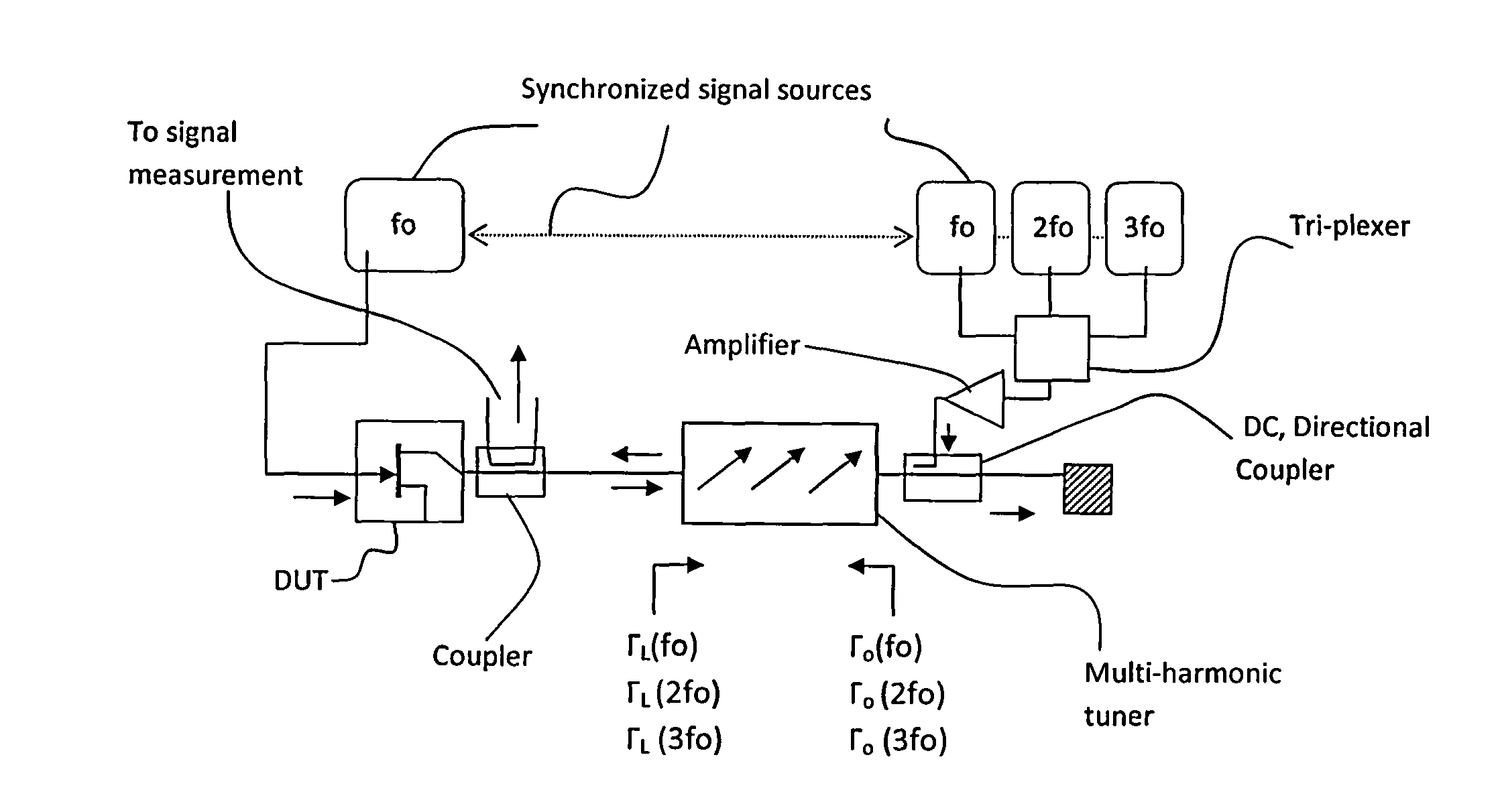
[0048]The present invention is about reducing the power requirements in the circuit of the active power injection into the DUT. As already shown an active injection system, consisting of an “active loop” or “two sources”, uses a (typically) 50Ω generator (the circulator in FIG. 3 or the directional coupler in FIG. 8 are both components with 50Ω internal impedance) to inject RF power into the output port of the DUT, which is a low value impedance of typically 0.5 to 2Ω. FIG. 6 illustrates the base of the power transfer calculations. In case of FIG. 6a (no transformer) the power delivered from the source Vo to the load R1 is: P1=Vo2*R1 / (R1−Ro)2. In the case of FIG. 6b (transformer 1:n included) the power delivered from the source Vo to R1 is: P1=Vo2*n2*R1 / (Ro−n2*R1)2. The ratio of power delivered to R1 directly or through a transformer is then: P1(direct) / P1 (transformed)=(Ro÷n2*R1)2 / (n2*(R1−Ro)2). In a typical case of R1=1Ω, Ro=50Ω, n=7, this ratio becomes: P1.direct / P1.transf=1 / 13=0...
PUM
Abstract
A method and test setup for reducing the RF power requirement in active load pull uses impedance tuners between the output of the test transistor and the active RF power injection network. The active network uses either a closed loop (active load) configuration or an open loop network employing split or synchronized signal sources. The impedance tuners are wideband (fundamental) tuners, harmonic rejection tuners or multi-harmonic tuners. A 7:1 transforming ratio of the tuners represents the best compromise between power matching and tuner loss, yielding a reduction of 11dB in power requirements from the active load or the synchronized source(s); if only the fundamental signal is injected at the output of the DUT, a multi-harmonic tuner or a harmonic rejection tuner is used for independent harmonic tuning; if multiple harmonic signals are injected, a multi-harmonic tuner is used and creates passive harmonic loads while reducing at the same time the power requirements from the harmonic injection sources.
Description
PRIORITY CLAIM[0001]Not applicableCROSS-REFERENCE TO RELATED ARTICLES[0002][1] Product Note 42, “Active Modules for harmonic load pull measurements”, Focus Microwaves, April 1997[0003][2] U.S. Pat. No. 7,135,941, Triple probe automatic slide screw load pull tuner and method.[0004][3]U.S. Pat. No. 6,297,649, Harmonic rejection load tuner.[0005][4] Product Note 79, “MPT, a universal Multi-Purpose Tuner”, Focus Microwaves, October 2004.[0006][5] Datasheet, XIANGYU COMMUNICATION TECHNOLOGY CO, LTD.[0007][6]“Overcoming Nonlinear Measurement Challenges”, Application Note, Tektronix Corp.[0008][7] Application Note 6, “Load Pull Measurements on very low impedance transistors”, Focus Microwaves, November 1993, Tables 4a, 4b, frequency points: 1, 2, 3 GHz.[0009][8]“A new load-pull characterization method for microwave power transistors”, Y. Takayama, 1976 IEEE-MTT-S symposium, pp. 218-220, June 1976.[0010][9] Cascading Tuners For High-VSWR And Harmonic Load Pull, Note 5C-081, Maury Microwave ...
Claims
Application Information
Patent Timeline
Application Date:The date an application was filed.
Publication Date:The date a patent or application was officially published.
First Publication Date:The earliest publication date of a patent with the same application number.
Issue Date:Publication date of the patent grant document.
PCT Entry Date:The Entry date of PCT National Phase.
Estimated Expiry Date:The statutory expiry date of a patent right according to the Patent Law, and it is the longest term of protection that the patent right can achieve without the termination of the patent right due to other reasons(Term extension factor has been taken into account ).
Invalid Date:Actual expiry date is based on effective date or publication date of legal transaction data of invalid patent.