Drum type laundry machine
a drum type and washing machine technology, applied in the direction of washing machines with receptacles, other washing machines, textiles and paper, etc., can solve the problems of loss of energy, excessive noise, and complicated fabrication process of conventional stators b>6/b> using the above described dividable core dc, etc., and achieve the effect of low weight and stable mounting
- Summary
- Abstract
- Description
- Claims
- Application Information
AI Technical Summary
Benefits of technology
Problems solved by technology
Method used
Image
Examples
first embodiment
[0076]First, the coupling structure of the stator according to the present invention will be described in detail with reference to FIGS. 5 and 6.
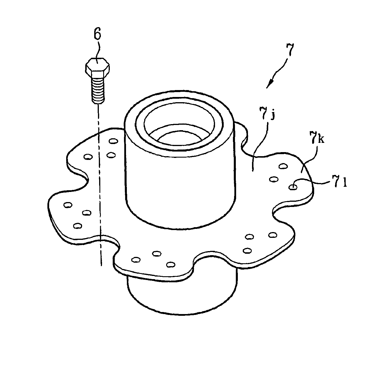
[0077]In the present embodiment, the bearing housing 7 includes a body 7b having a substantially sleeve shape, i.e. a cylindrical shape, and the hub portion 7c formed at a side of the body 7b and coupled with the stator 6. The stator 6 is directly connected to the bearing housing hub portion 7c.
[0078]The bearing housing hub portion 7c is exposed from the outer surface of the tub base 2a after the bearing housing 7 is integrally formed with the tub 2 by insert-molding. As shown, the bearing housing hub portion 7c may have a radius larger than that of the bearing housing body 7b.
[0079]The bearing housing hub portion 7c has a seating portion 7d on which the stator 6 will be seated. The seating portion 7d has a flat plane shape to allow the stator 6 to be seated thereon at a position perpendicular to the shaft 4.
[0080]Although the stator 6 of...
third embodiment
[0091]Hereinafter, a further coupling structure of the stator according to the present invention will be described with reference to FIG. 9. Although most configurations of the present embodiment are identical to those of the above described embodiments, in the present embodiment, the radius of the bearing housing body 7b is larger than the radius of the bearing housing hub portion 7i; and the stator 6 is directly connected to the bearing housing body 7b.
[0092]In the present embodiment, the stator 6 is inserted into the bearing housing hub portion 7c, and coupled with the bearing housing 7 via the coupling bores 143b formed in the coupling portions 143 of the stator 6 and coupling holes 7e formed in the bearing housing body 7b.
[0093]Similar to the above described embodiments, the shape of the outer peripheral surface of the bearing housing hub portion 7c matches with the shape of the inner peripheral surface of the stator 6, such that the bearing housing hub portion 7c can support...
fourth embodiment
[0096]FIG. 10 is a perspective view illustrating the coupling structure of the stator according to the present invention.
[0097]In the present embodiment, the tub base 2a to be coupled with the stator 6 has a hub portion 2b protruding from the outer surface of the base 2a by a predetermined length. The hub portion 2b is a portion of the tub 2. The bearing housing 7 is insert-molded through the hub portion 2a, so as to be integrally formed with the tub 2.
[0098]As shown in FIG. 10, the outer peripheral surface of the hub portion 2b preferably has a repeated uneven pattern in a circumferential direction thereof. Specifically, the hub portion 2b has concave and convex portions alternately arranged in a circumferential direction thereof. The inner peripheral surface of the stator 6 has a shape corresponding to that of the outer peripheral surface of the hub portion 2b.
[0099]With this configuration, the stator 6 is coupled with the tub base 2a as it is inserted into the hub portion 2b. Fo...
PUM
| Property | Measurement | Unit |
|---|---|---|
| angle | aaaaa | aaaaa |
| distance | aaaaa | aaaaa |
| shape | aaaaa | aaaaa |
Abstract
Description
Claims
Application Information
 - R&D
- Intellectual Property
- Life Sciences
- Materials
- Tech Scout
- Unparalleled Data Quality
- Higher Quality Content
- 60% Fewer Hallucinations
Browse by: Latest US Patents, China's latest patents, Technical Efficacy Thesaurus, Application Domain, Technology Topic, Popular Technical Reports.
© 2025 PatSnap. All rights reserved.Legal|Privacy policy|Modern Slavery Act Transparency Statement|Sitemap|About US| Contact US: help@patsnap.com


