Method for manufacturing a three-dimensional object

a three-dimensional object and manufacturing method technology, applied in the direction of additive manufacturing processes, electric/magnetic/electromagnetic heating, instruments, etc., can solve the problems of difficult to measure up to the present the mechanical properties of the member, for example the coefficient of elasticity, and the above method is, however, quite complex, so as to achieve simple, rapid and precise detection of special mechanical properties.

Inactive Publication Date: 2013-08-06
EOS ELECTRO OPTICAL SYST
View PDF6 Cites 60 Cited by
  • Summary
  • Abstract
  • Description
  • Claims
  • Application Information

AI Technical Summary

Benefits of technology

[0005]It is an object of the invention to provide a method of manufacturing a three-dimensional object, especially a laser sintering method, which allows a simple, rapid and precise detection of especially mechanical properties of the members.

Problems solved by technology

The mechanical properties of members, for example the coefficient of elasticity, however, are difficult to measure up to the present, because the necessary equipment is a complex one.
The above method is, however, quite complex.

Method used


Image

  • Method for manufacturing a three-dimensional object
  • Method for manufacturing a three-dimensional object
  • Method for manufacturing a three-dimensional object

Examples


first embodiment

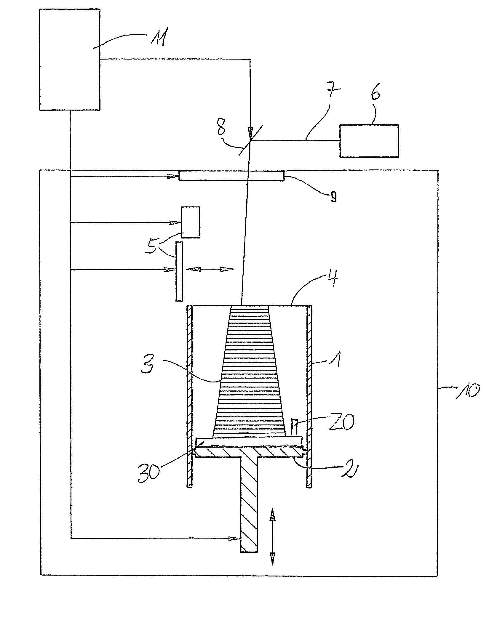
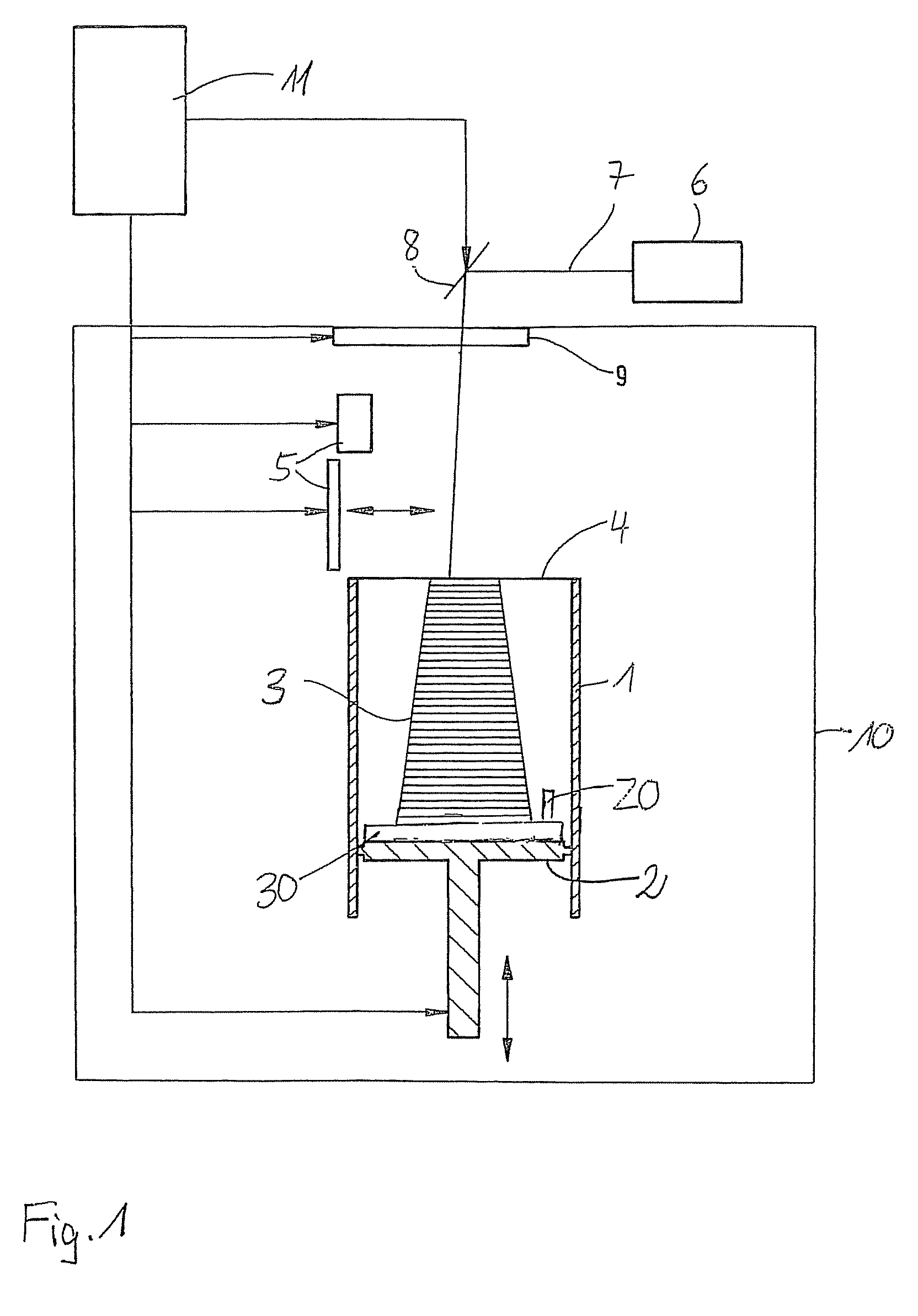
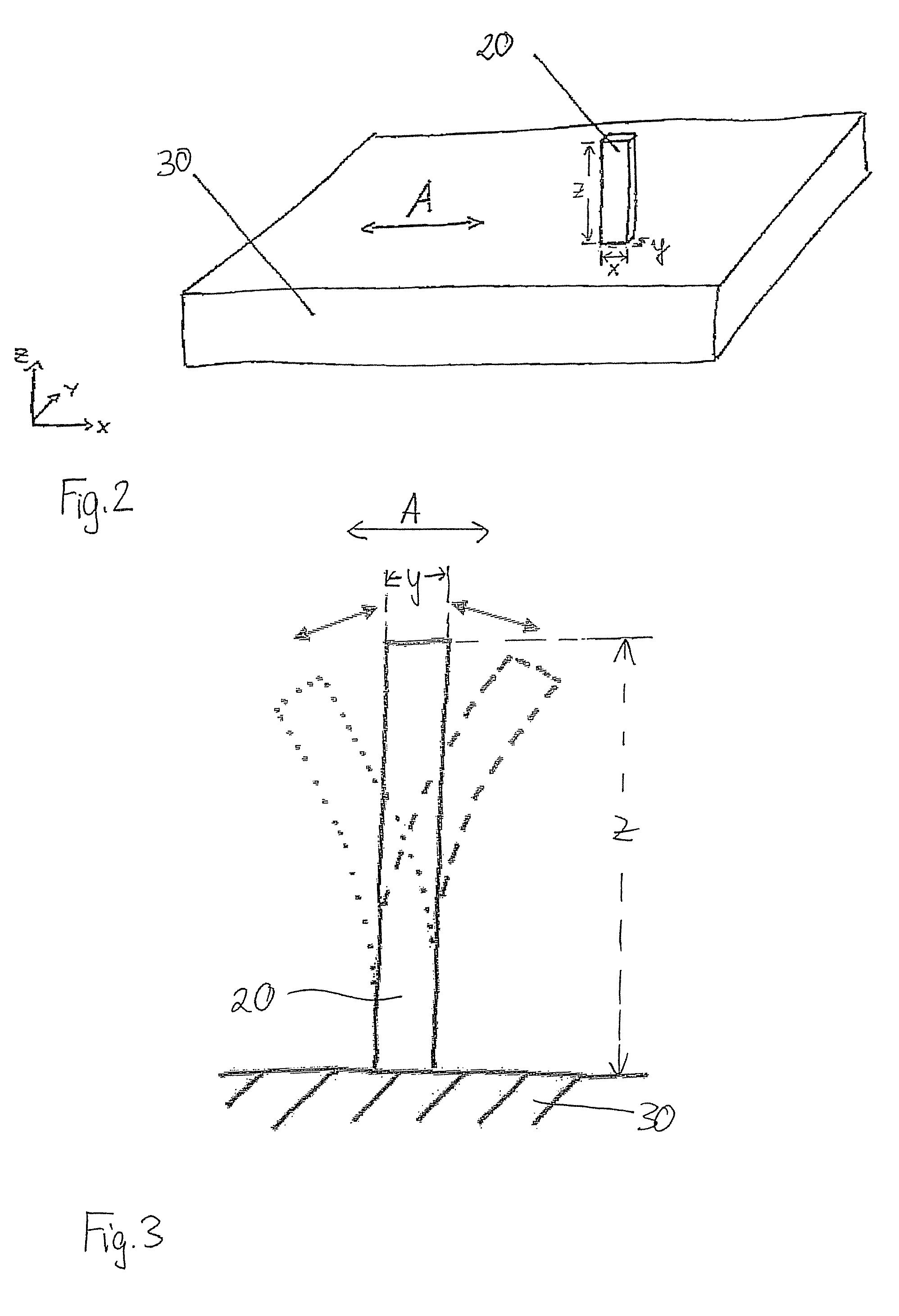
[0014]In the method according to the present invention as depicted schematically in FIG. 1, a test specimen 20 is co-built when building the object 3 to be produced itself. This test specimen 20 is excited to oscillations after the manufacture of the object 3, and then, the natural frequencies of the oscillating specimen 20 are determined. From those ones, properties of the manufactured object 3, for example the coefficient of elasticity, are determined. The CAD data which contain the geometry of the test specimen, may be contained in the same data set which also contains the object data, or the CAD data can be chosen, for example from a library, and added.

[0015]The test specimen 20 can be built anywhere at a suitable place in the building space defined by the container wall and the support. There is no need to connect it to the support 2 and / or the object 3. According to a preferred embodiment of the method, the test specimen 20 is not built freely in the building space, but on a ...

second embodiment

[0030]According to the method, the test specimen is not co-built when manufacturing the desired object, but is used for quality determination and calibration of the laser sintering device and is built separately from the object itself in a separate building process. For this purpose, one or several test specimen are built before the start of a series job, and their natural frequency spectra are analyzed and compared to the one of a reference specimen. Subsequently, the parameters of the laser sintering device are adapted accordingly, so that the objects to be produced have the desired properties. A check can be carried out by means of co-building of test specimen in the series production.

[0031]The method is not restricted to a laser sintering process. It is applicable to all layer building methods, for example to stereolithography which uses, instead of a powdery material, a liquid, light-setting resin, to three-dimensional printing according to which the powdery building material i...


PUM

PropertyMeasurementUnit
mechanical oscillationsaaaaaaaaaa
natural frequenciesaaaaaaaaaa
geometric shapeaaaaaaaaaa

Abstract

Method of manufacturing a three-dimensional object according to which the object is built layer-wise by solidification of a building material, wherein a test specimen is built which is excited to oscillate after being built and wherein natural frequencies of the oscillations are determined.

Description

BACKGROUND OF THE INVENTION[0001]The invention relates to a method of manufacturing a three-dimensional object. Especially, the invention relates to a method of laser sintering of members.[0002]Increasingly, selective laser sintering is not only used for the manufacturing of prototypes or of small series of members, but also for the series production of fully operative members. As a rule, the manufactured members have to undergo quality tests, especially in order to test their mechanical properties. The mechanical properties of members, for example the coefficient of elasticity, however, are difficult to measure up to the present, because the necessary equipment is a complex one.[0003]It is known to the applicant that test specimen, for example tensile bars, can be manufactured by the laser sintering method and can be mechanically measured afterwards in order to derive information about the properties, for example the coefficient of elasticity of a member to be produced, which prope...

Claims


Application Information

Patent Timeline
Patent Type & Authority Patents(United States)
IPC IPC(8): B29C35/08B29C41/52B29C41/02
CPCB29C67/0077G01N29/30G01N29/12G01N2291/0232B29C64/153B33Y70/00B33Y30/00B33Y80/00Y02P10/25B22F10/28
Inventor PHILIPPI, JOCHENSCHILLING, ALEXANDER
Owner EOS ELECTRO OPTICAL SYST
Why Eureka
Try Eureka