
Enhanced public safety communication system

a communication system and public safety technology, applied in the field of communication systems, can solve the problems of affecting the ability to manage multiple communication devices, non-mission critical devices do not provide a user interface,

Active Publication Date: 2013-08-06
MOTOROLA SOLUTIONS INC
View PDF35 Cites 45 Cited by
  • Summary
  • Abstract
  • Description
  • Claims
  • Application Information

AI Technical Summary

Problems solved by technology

These secondary, non-mission critical devices do not provide a user interface for high stress environments and can become a distraction to the user during a mission critical situation.
Particularly in high stress emergency situations, the ability to manage numerous communication devices can become problematic.

Method used


Image

  • Enhanced public safety communication system
  • Enhanced public safety communication system
  • Enhanced public safety communication system

Examples


examples

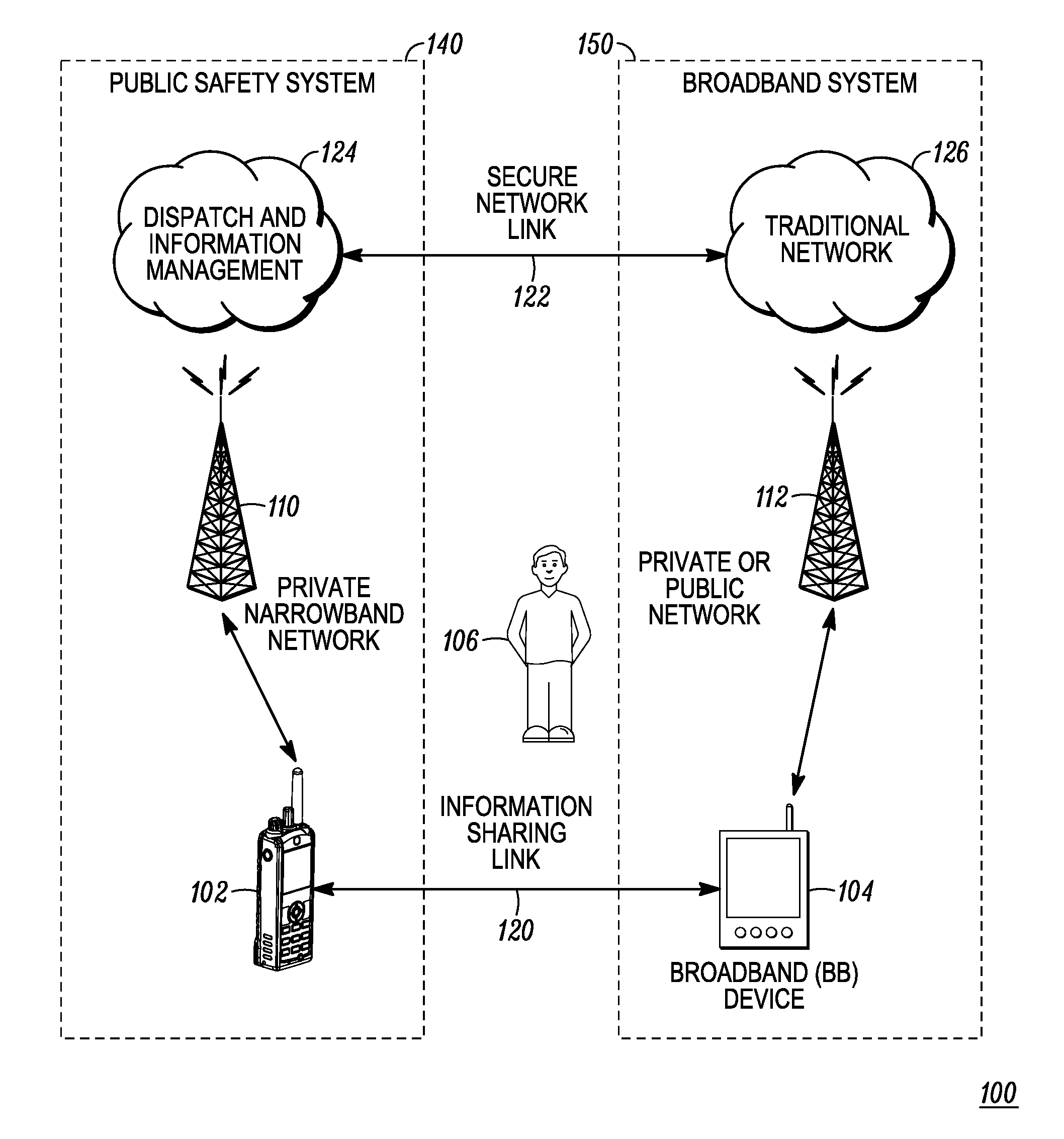
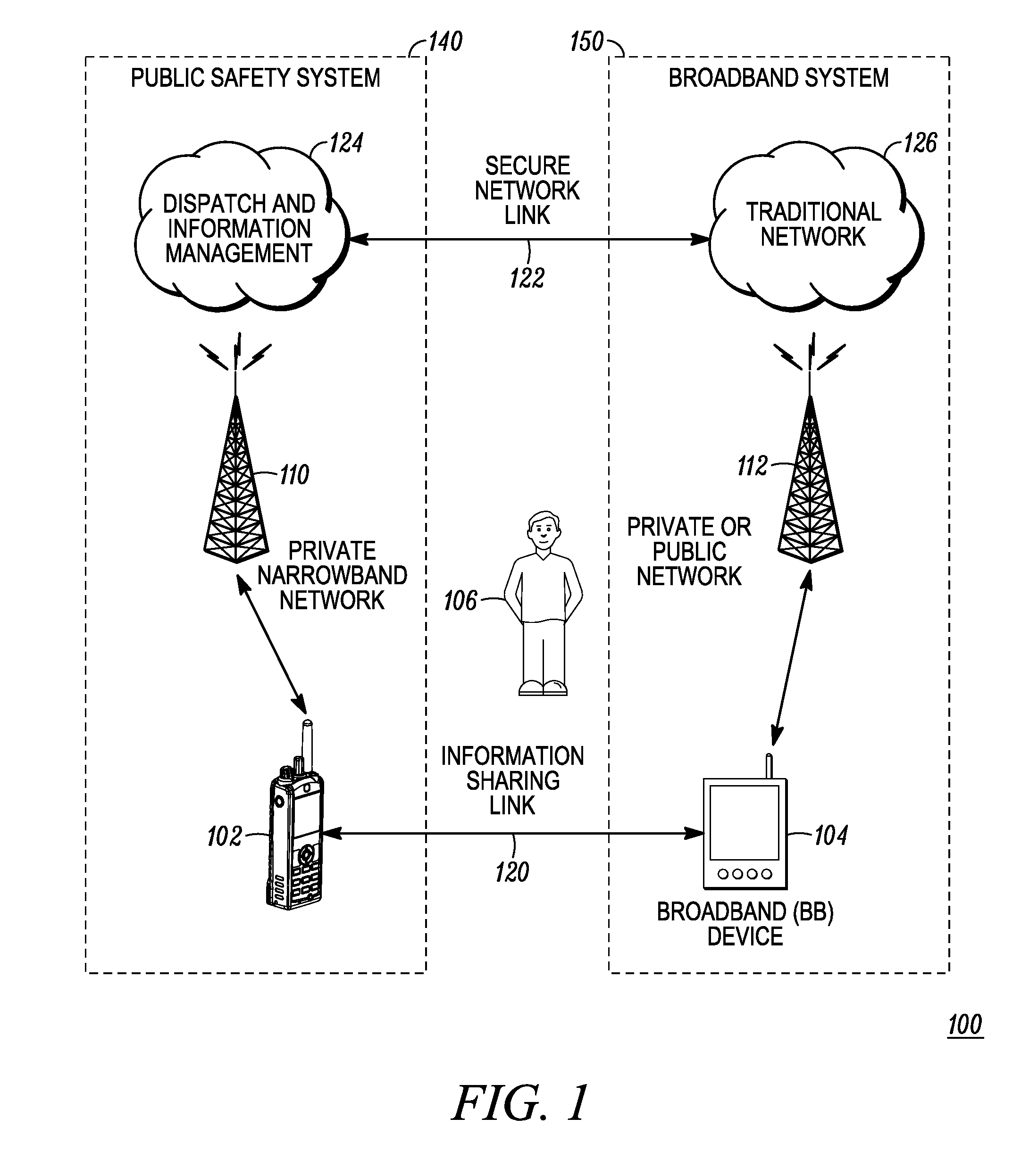
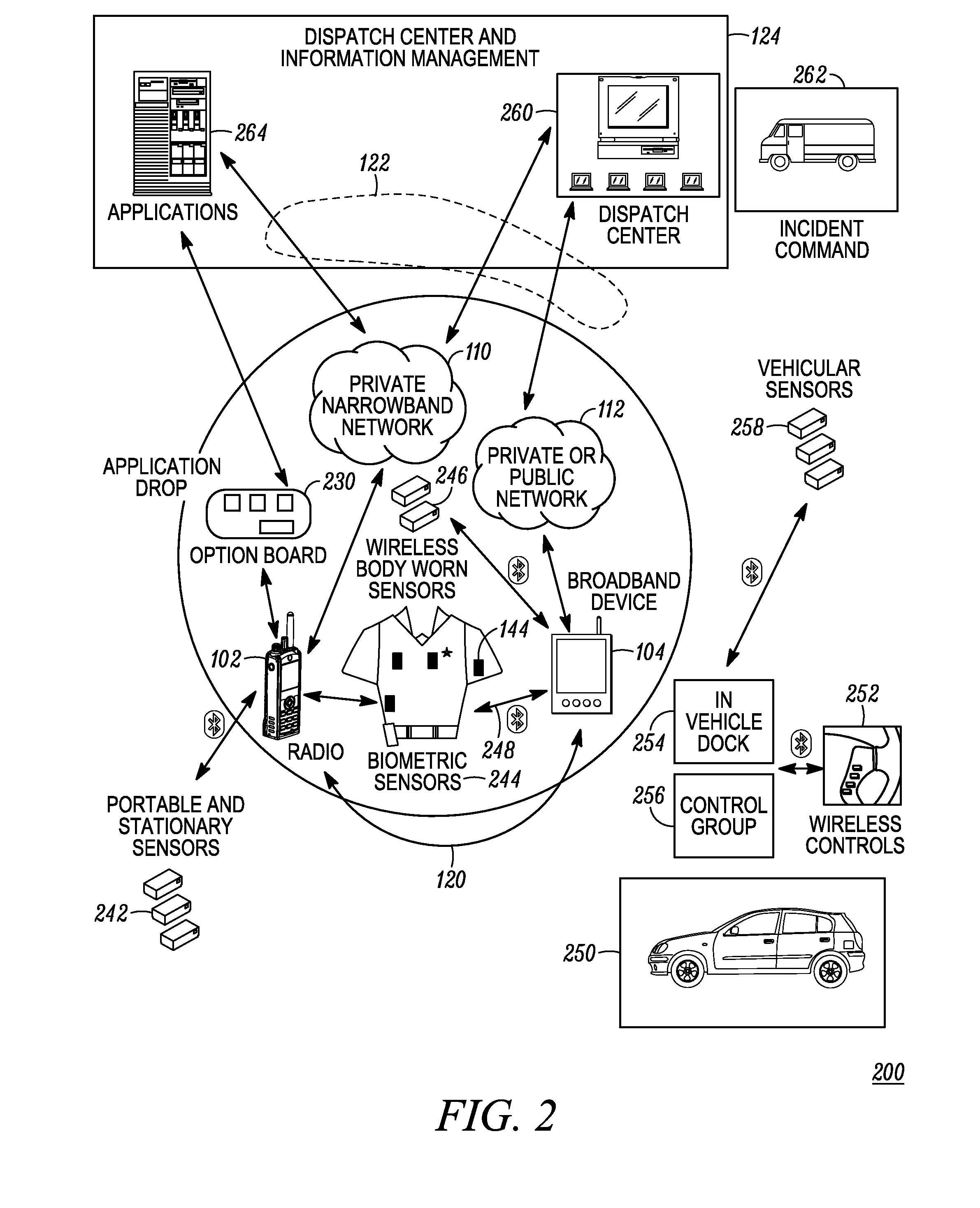
[0056]The following examples describe various embodiments of partnered device interaction for the communication system operating within a public safety environment. For the following examples, the first device is the narrowband device 102 operating within a public safety system and is referred to as a radio, while a second device is the broadband device 104 operating in either a private or public network within a broadband system and is referred to as a personal digital assistant (PDA).

example # 1

Example #1

Call Received

[0057]Radio identifies a peer device and vice versa[0058]Devices associate either with a proprietary or common standards based protocol (example: Bluetooth)[0059]Post association, the devices share a functional list in some understood proprietary protocol (example: XML)[0060]Radio receives a call from a specific user[0061]The two devices can manage this event in three different ways in accordance with the device interaction scenario.

[0062]Device Interaction Scenario #1[0063]Radio shares that radio ID with a second device (example: PDA) and processes the call indifferent to the fact that the radio shared the information with the PDA; i.e. radio enables intelligent lights, and any applicable tones[0064]Second device (example: PDA) utilizes the caller ID and the fact that the Call Receive event occurred to process additional activity[0065]The PDA processes any call receive audible tones and enables the call receive intelligent lighting for some pre-set of time (i...

example # 2

Example #2

Remote Control

[0081]Radio identifies a peer device and vice versa[0082]Devices associate either with a proprietary or common standards based protocol (example: Bluetooth)[0083]Post association, the devices share a functional list in some understood proprietary protocol (example: XML)[0084]Second device (example: PDA) offers an application that can drive events on the radio device[0085]Channel changes, volume control, call initiation, etc.[0086]The different DIS procedures would vary with the coordination of the radio LEDs or color display showing the channel change or call initiation event.[0087]The call initiated from the PDA would still be controlled on the radio via the time out timers[0088]The radio would be capable of communicating its internal status (i.e. result of the call time out timer) back to the PDA


PUM


Abstract

A communication system (100) provides collaboration between narrowband communication devices (102) and broadband communication devices (104) operating over different networks. The communication devices (102, 104) are linked to provide peer-to-peer communication that supports the dissemination of public safety information to a public safety personnel user utilizing the devices. Applications within the devices (102, 104) automatically control features amongst the plurality of devices for redundancy of critical information, removal of non-critical information and power management. Context information can also be examined and shared between amongst the devices.

Description

CROSS REFERENCE TO RELATED APPLICATIONS[0001]This application is related to co-pending U.S. patent applications Ser. Nos. 12 / 749,142 and 12 / 749,248, filed concurrently herewith and commonly assigned to Motorola, Inc.FIELD OF THE DISCLOSURE[0002]The present disclosure relates generally to communication systems, and more particularly, to the enhancement of public safety communication systems through linkage with additional non public safety communication devices.BACKGROUND[0003]Public safety personnel, such as police officers, firefighters, paramedics and the like typically utilize numerous communication devices while working in the field. Public safety communication devices include, for example, mobile radios such as handheld radios and / or vehicular radios along with remote accessories, such as remote microphones, speakers, earpieces, headsets and the like. These primary, mission critical devices and the infrastructure to support their operation are typically realized in the form of ...

Claims


Application Information

Patent Timeline
Patent Type & Authority Patents(United States)
IPC IPC(8): G08C17/00H04B7/00H04M1/00H04M11/04H04J3/00H04W4/20H04W4/21H04W4/90
CPCH04M3/42178H04W4/20H04W4/206H04W4/203H04W76/007H04W84/08H04W4/22H04L67/104H04W4/21H04W76/50H04W4/90H04M3/42
Inventor KLEIN, DAVID E.ALAZRAKI, SCOTT M.BROOKS, ERIC D.YOUNG, STEVEN E.MONKS, DEBORAH J.BLANCO, ALEJANDRO G.
Owner MOTOROLA SOLUTIONS INC
Learn More