
Nasogastric tube for use during an ablation procedure

a technology of nasogastric tubes and ablation procedures, which is applied in the field of nasogastric tubes, can solve the problems of unintended air embolism, discontinuous fat pads, etc., and achieve the effect of reducing the incidence of thermal injury to the esophagus and avoiding thermal esophageal injury

Active Publication Date: 2013-08-13
MALONEY JAMES D
View PDF47 Cites 9 Cited by
  • Summary
  • Abstract
  • Description
  • Claims
  • Application Information

AI Technical Summary

Benefits of technology

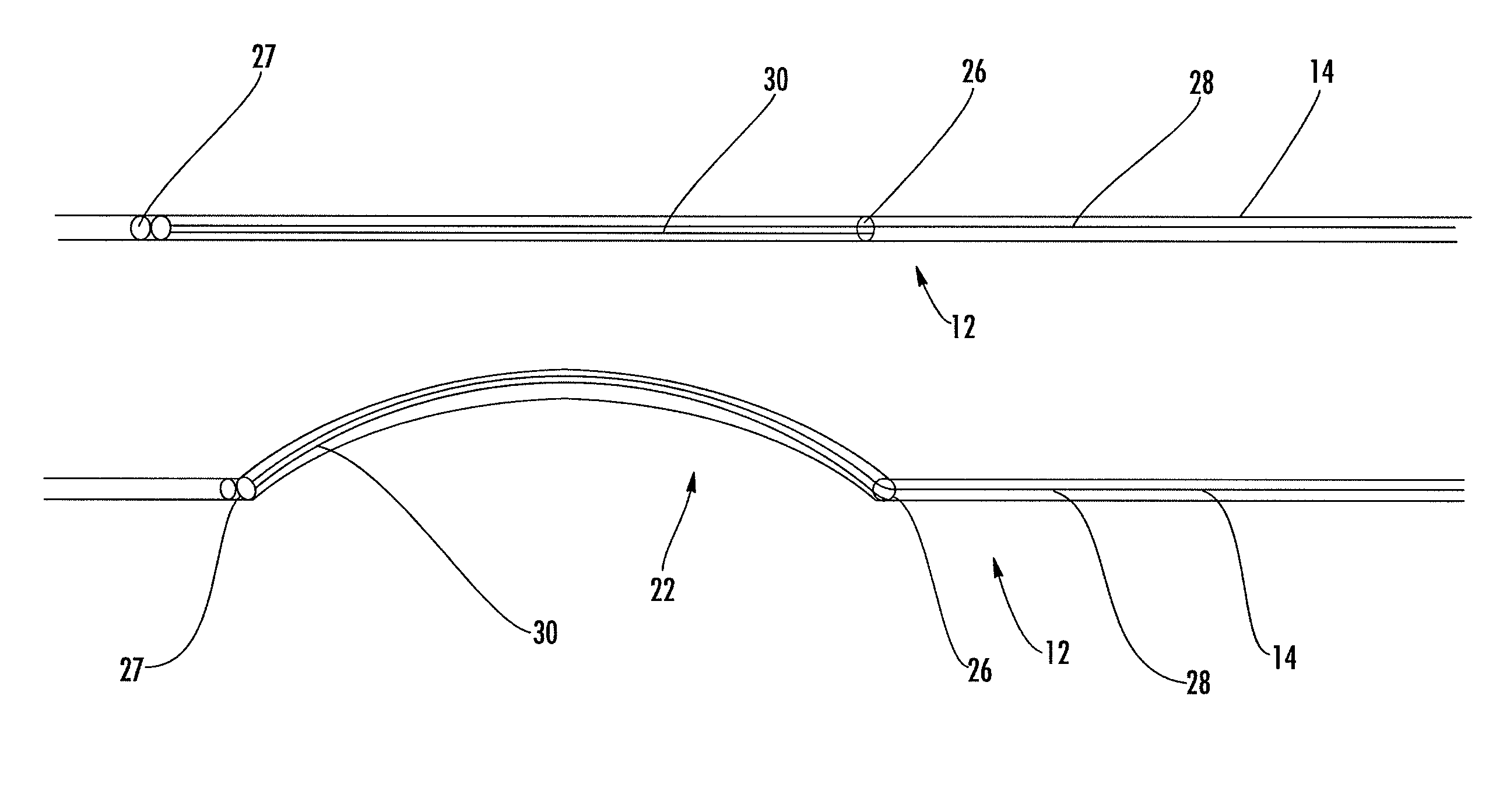
The present invention provides a nasogastric tube that can be used to deflect the esophagus during a medical procedure to reduce the risk of injury to the esophagus. The nasogastric tube has multiple lumens that can receive instruments to monitor the position and physical properties of the esophagus, as well as assist in positioning the tube within the esophagus. The esophageal deflector is placed within one of the lumens and can deflect a portion of the tube to avoid injury to the esophagus. This invention helps to safely perform ablation procedures and minimize harmful side effects on the patient.

Problems solved by technology

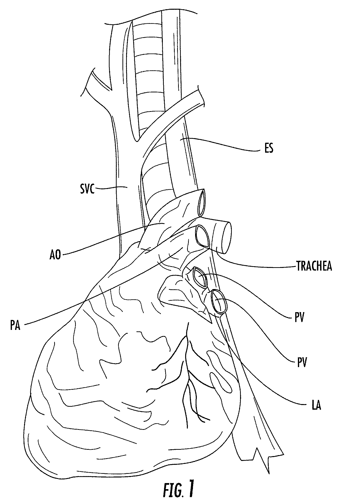
Although most patients have a small fat pad separating the posterior left atrium and esophagus, this fat pad is often discontinuous.
Due to the close proximity of the esophagus and the left atrium, ablation along the posterior left atrium may result in unintended thermal injury to the esophagus and subsequent fatal esophageal-atrial fistula presenting as a fatal complication 1-3 weeks following left atrial ablation.
An esophageal-atrial fistula can cause an air embolism with a stroke, mediastinitis, or GI bleeding having high mortality rates.
However, these precautionary approaches have proven to be unreliable and / or likely to compromise the ablation procedure.
As a result, static imaging techniques may be inadequate to monitor the position of the esophagus due to the mobility of the esophagus.
Transesophageal echo probes have been utilized in attempts to deflect or mobilize the retrocardiac portion of the esophagus away from ablation sites, but have had limited success due to the bulkiness of the device and the inability of the curved distal tip of the probe to effectively deflect the esophagus.

Method used


Image

  • Nasogastric tube for use during an ablation procedure
  • Nasogastric tube for use during an ablation procedure
  • Nasogastric tube for use during an ablation procedure

Examples


Embodiment Construction

[0021]The present inventions now will be described more fully hereinafter with reference to the accompanying drawings, in which some, but not all embodiments of the invention are shown. Indeed, this invention may be embodied in many different forms and should not be construed as limited to the embodiments set forth herein; rather, these embodiments are provided so that this disclosure will satisfy applicable legal requirements. Like numbers refer to like elements throughout.

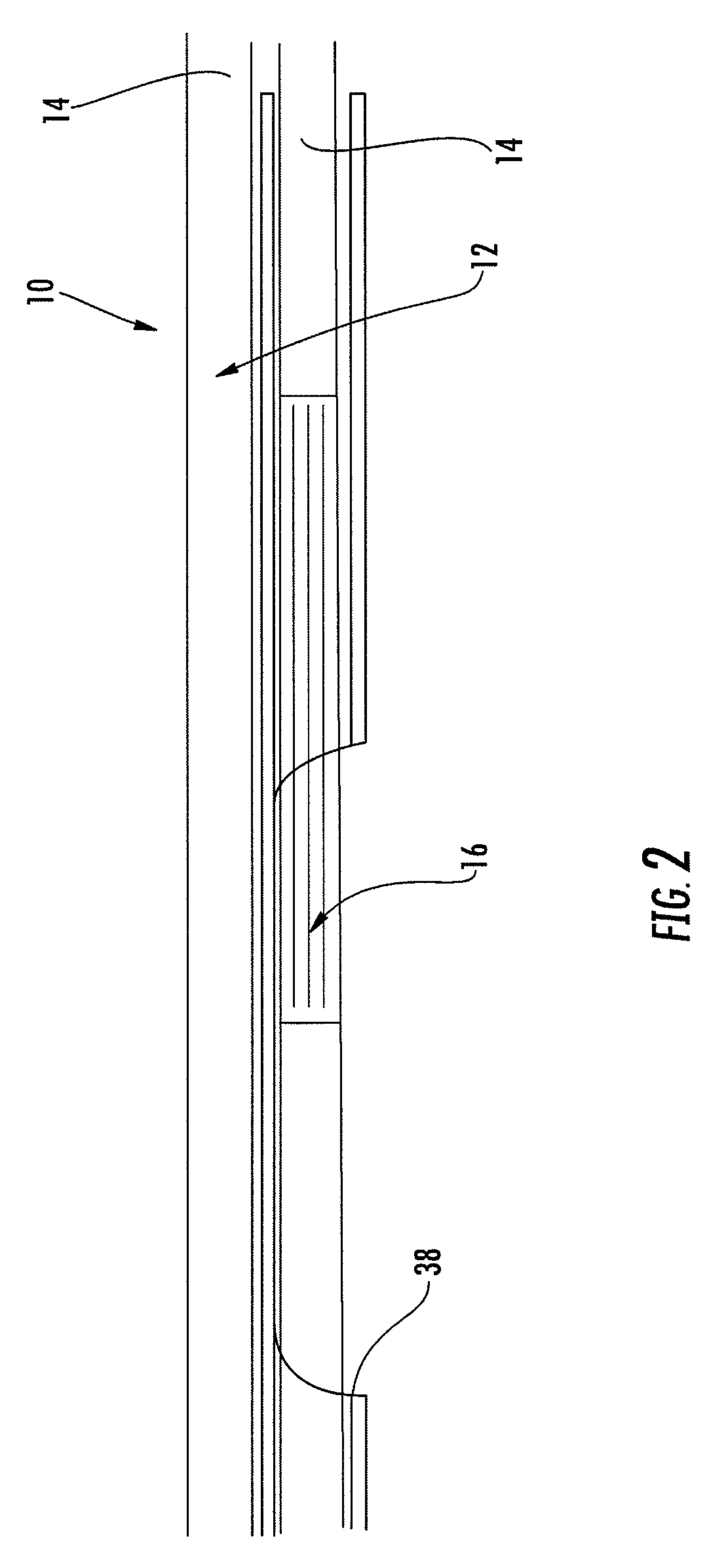
[0022]Referring to FIG. 2, there is shown a nasogastric tube 10 according to one embodiment of the present invention. In general, the nasogastric tube 10 includes at least one lumen 14 for receiving an instrument therein. According to one embodiment, an esophageal deflector 12 is positioned within the lumen 14 and is configured to deflect the esophagus during an ablation procedure. For example, the esophageal deflector 12 may be configured to deflect a portion of the nasogastric tube 10 proximate to a retrocardia...


PUM


Abstract

Embodiments of the present invention provide a nastogastric tube for deflecting an esophagus during an ablation procedure. According to one embodiment, the nasogastric tube includes a tube comprising at least one lumen having proximal and distal ends, and an esophageal deflector positioned within the at least one lumen and configured to deflect a portion of the tube between the proximal and distal ends. The esophageal deflector is configured to deflect the portion of the tube proximate to a retrocardiac portion of the esophagus such that the retrocardiac portion of the esophagus is deflected away from an ablation site.

Description

FIELD OF THE INVENTION[0001]Embodiments of the present invention relate generally to a nasogastric tube and, more particularly, to a nasogastric tube for deflecting the esophagus and monitoring various properties of the esophagus during an ablation procedure.BACKGROUND OF THE INVENTION[0002]Esophageal tubes, probes, balloons, and other devices have been used to monitor internal physiologic function, decompress all portions of the alimentary tract, and protect the airway in sedated patients undergoing surgical procedures. It is currently common medical practice to use a nasogastric tube in most patients requiring mechanical ventilation during surgical procedures, and to use a nasogastric tube to mark the anatomic relationships between the left atrium and the esophagus in patients undergoing atrial fibrillation ablation with general anesthesia and or conscious sedation procedures. Marking the esophagus during atrial fibrillation (left atrial) ablation has gained prominence because of ...

Claims


Application Information

Patent Timeline
Patent Type & Authority Patents(United States)
IPC IPC(8): A61M29/00A61M31/00A61M37/00
CPCA61B18/1492A61B2017/00101A61B2018/00214A61B2018/00267
Inventor MALONEY, JAMES D.
Owner MALONEY JAMES D
Learn More