
Apparatus and method of energy efficient illumination

a technology of illumination apparatus and energy-saving technology, applied in the direction of lighting and heating apparatus, lighting device details, light sources, etc., can solve the problems of little benefit of high-level lighting or illumination between late evening and early morning hours, and achieve the effect of improving the energy efficiency of lighting systems

Active Publication Date: 2013-08-13
EXPRESS IMAGING SYST
View PDF82 Cites 43 Cited by
  • Summary
  • Abstract
  • Description
  • Claims
  • Application Information

AI Technical Summary

Benefits of technology

The patent describes a lighting system that adjusts its level of light output based on the time of day and the level of sunlight. This ensures that the lighting system is not affected by artificial light, such as car headlights, and can adjust its level of light output accordingly. The system also takes into account changes in natural lighting conditions, such as snow fall, to ensure optimal performance. Additionally, the system can control multiple luminaires simultaneously, reducing the need for individual adjustments and improving overall performance.

Problems solved by technology

High level lighting or illumination between the late evening and early morning hours provides little benefit.

Method used


Image

  • Apparatus and method of energy efficient illumination
  • Apparatus and method of energy efficient illumination
  • Apparatus and method of energy efficient illumination

Examples


Embodiment Construction

[0045]In the following description, certain specific details are set forth in order to provide a thorough understanding of various disclosed embodiments. However, one skilled in the relevant art will recognize that embodiments may be practiced without one or more of these specific details, or with other methods, components, materials, etc. In other instances, well-known structures associated with luminaires and imaging devices have not been shown or described in detail to avoid unnecessarily obscuring descriptions of the embodiments.

[0046]Unless the context requires otherwise, throughout the specification and claims which follow, the word “comprise” and variations thereof, such as “comprises” and “comprising,” are to be construed in an open, inclusive sense that is as “including, but not limited to.”

[0047]Reference throughout this specification to “one embodiment” or “an embodiment” means that a particular feature, structure or characteristic described in connection with the embodim...


PUM


Abstract

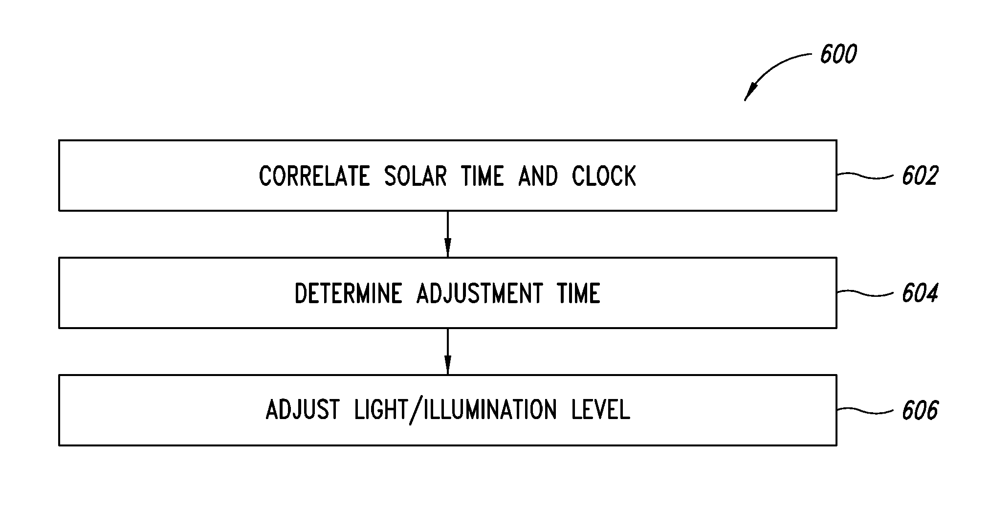
An illumination system correlates solar time to a clock and controls lighting or illumination based on time. The illumination system may turn ON light source(s) at a first level at a turn ON time, correlated to be around or at dusk, and turn OFF light source(s) at a turn OFF time, correlated to be around or at dawn. The illumination system may reduce a level of light output, and hence power consumption, at a time after turning ON a light source, and increases the level of light output at a time prior to turning OFF the light source. Turn ON, turn OFF, decrease and increase times may be determined based on recent levels of light or illumination in the environment, for example via average or median levels over a number of previous daily cycles. Filtering may eliminate aberrant events.

Description

CROSS-REFERENCE TO RELATED APPLICATIONS[0001]This application claims benefit under 35 U.S.C. 119(e) to U.S. Provisional Patent Application Ser. No. 61 / 180,017, filed May 20, 2009, U.S. Provisional Patent Application Ser. No. 61 / 333,983, filed May 12, 2010, and U.S. Provisional Patent Application Ser. No. 61 / 346,263, filed May 19, 2010.BACKGROUND[0002]1. Technical Field[0003]The present disclosure generally relates to the field of illumination devices and, more particularly, to control of illumination to improve energy efficiency.[0004]2. Description of the Related Art[0005]Energy conservation has become of ever increasing importance. Efficient use of energy can result in a variety of benefits, including financial benefits such as cost savings and environmental benefits such as preservation of natural resources and reduction in “green house” (e.g., CO2) gas emissions.[0006]Residential, commercial, and street lighting which illuminate interior and exterior spaces consume a significant...

Claims


Application Information

Patent Timeline
Patent Type & Authority Patents(United States)
IPC IPC(8): H05B39/04H05B41/36H05B37/02F21V23/04
CPCH05B37/0218H05B37/0281Y02B20/46Y02B20/42H05B47/11H05B47/16Y02B20/40
Inventor REED, WILLIAM G.
Owner EXPRESS IMAGING SYST
Learn More