Method of validating a biometric capture, notably a body print

a biometric and capture method technology, applied in the field of biometric capture, can solve the problems of false fingers, body prints, and inability to exclude the fact that fraud can take place, and achieve the effect of simple and quick implementation

Active Publication Date: 2013-08-13
IDEMIA IDENTITY & SECURITY FRANCE +1
View PDF17 Cites 4 Cited by
  • Summary
  • Abstract
  • Description
  • Claims
  • Application Information

AI Technical Summary

Benefits of technology

[0018]The method according to the invention is simple and quick to implement, it does not require the use of complex and costly hardware, and it is capable of providing the required information within a time period (less than a second) that is compatible with an individual identification process.
[0019]Furthermore, this method can give rise to various possibilities and variant implementations that allow for easy adaptation to various constraints. In particular, in a first implementation, it is possible to provide for said area of the body to be illuminated using at least two radiations including said at least two different respective wavelengths and for at least two reflectometry measurements in relation to said at least two different respective wavelengths to be carried out to measure the reflection rate of the tissues of said body area for said at least two wavelengths. In a second implementation, it is possible, on the other hand, to provide for said area of the body to be illuminated using a radiation including said at least two different respective wavelengths, for the at least two reflected radiations having said at least two wavelengths to be filtered from the reflected radiation, and for at least two reflectometry measurements aligned on said at least two different respective wavelengths to be carried out to measure the reflection rate of the tissues of said body area for said at least two wavelengths.

Problems solved by technology

These false fingers, which can certainly offer the formal appearance of the appropriate body print, do not, however, have all the electrical or chemical characteristics of a living finger.
However, it is not possible to exclude the fact that the fraud can take place with the proper body area of the individual that the defrauder would have previously amputated (in particular, cutting off a finger of the individual that the defrauder then applies to the fingerprint capture device).
However, the existing control methods often prove ill suited to this precise case of fraud because a body area that has been amputated loses the physical characteristics measured by these methods only after a certain time period, sufficiently long to allow a defrauder the time to amputate an area of the body of the individual, then go to the print capture device to use thereon the area of the body amputated.
However, it is improbable that the defrauder will amputate the body area in the same place where the print capture must be performed and in practice, between the moment when the body area is amputated and its use for the purposes of print capture, a time interval will elapse which, even if it is not very long (for example a few minutes, and a fortiori if it is several hours, even several days), will be sufficient for the oxygenation ratio of the hemoglobin to have decreased to a value very much lower than the living value.
This is a measurement process that is slow, notably because of the long time needed to carry out the measurement of the pulse, but it does lead to accurate information concerning the oxygenation rate of the arterial blood.
However, it is essential to consider that such precise information on the oxygenation rate of the arterial blood, while it can indeed be exploited in the context of a biometric identification of an individual targeted by the invention, would be excessive, because the precision of the information to which it would lead is not necessary to arrive at the biometric information sought; furthermore, the acquisition time for the useful information would be much too long and implementation relatively complex (modulation of the incident light, numerous processing operations to extract the pulsed information and spurious information), such that this known solution cannot be retained to implement a fast and economical process of biometric identification.
Also, optical analysis in transmission mode is not suited to the usual format of the biometric sensors currently used.

Method used


Image

  • Method of validating a biometric capture, notably a body print
  • Method of validating a biometric capture, notably a body print
  • Method of validating a biometric capture, notably a body print

Examples


Embodiment Construction

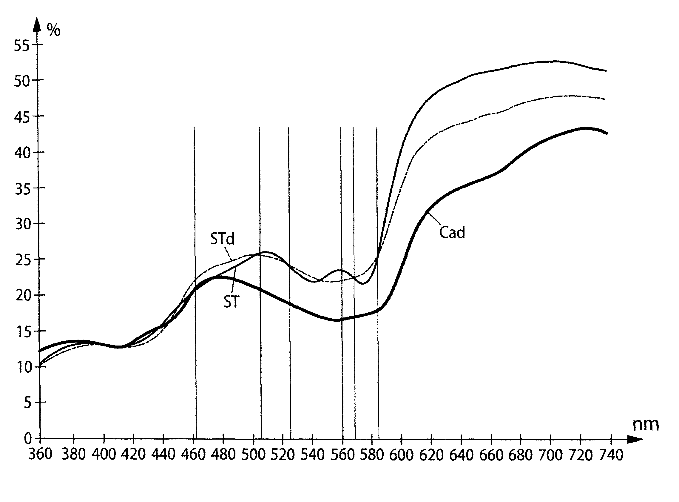
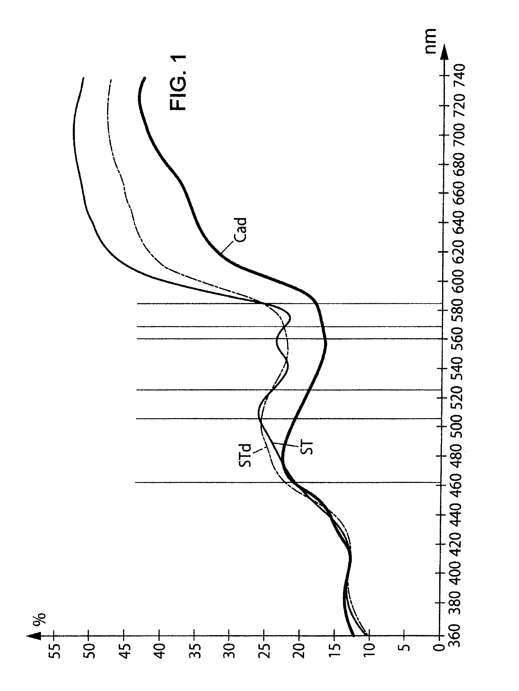
[0027]In FIG. 1, the curve “ST” represents, according to the wavelength of an incident electromagnetic radiation in a range of wavelengths between 360 nm and 740 nm, the reflection rate (as a percentage of the incident power) of an electromagnetic radiation for a standard living tissue.

[0028]In FIG. 1, the curve “STd” represents, according to the wavelength of an incident electromagnetic radiation in a range of wavelengths between 360 nm and 740 nm, the reflection rate (as a percentage of the incident power) of an electromagnetic radiation for a living tissue after application of a tourniquet for one minute.

[0029]In FIG. 1, the curve “Cad” represents, according to the wavelength of an incident electromagnetic radiation in a range of wavelengths between 360 nm and 740 nm, the reflection rate (as a percentage of the incident power) of an electromagnetic radiation for a cadavre.

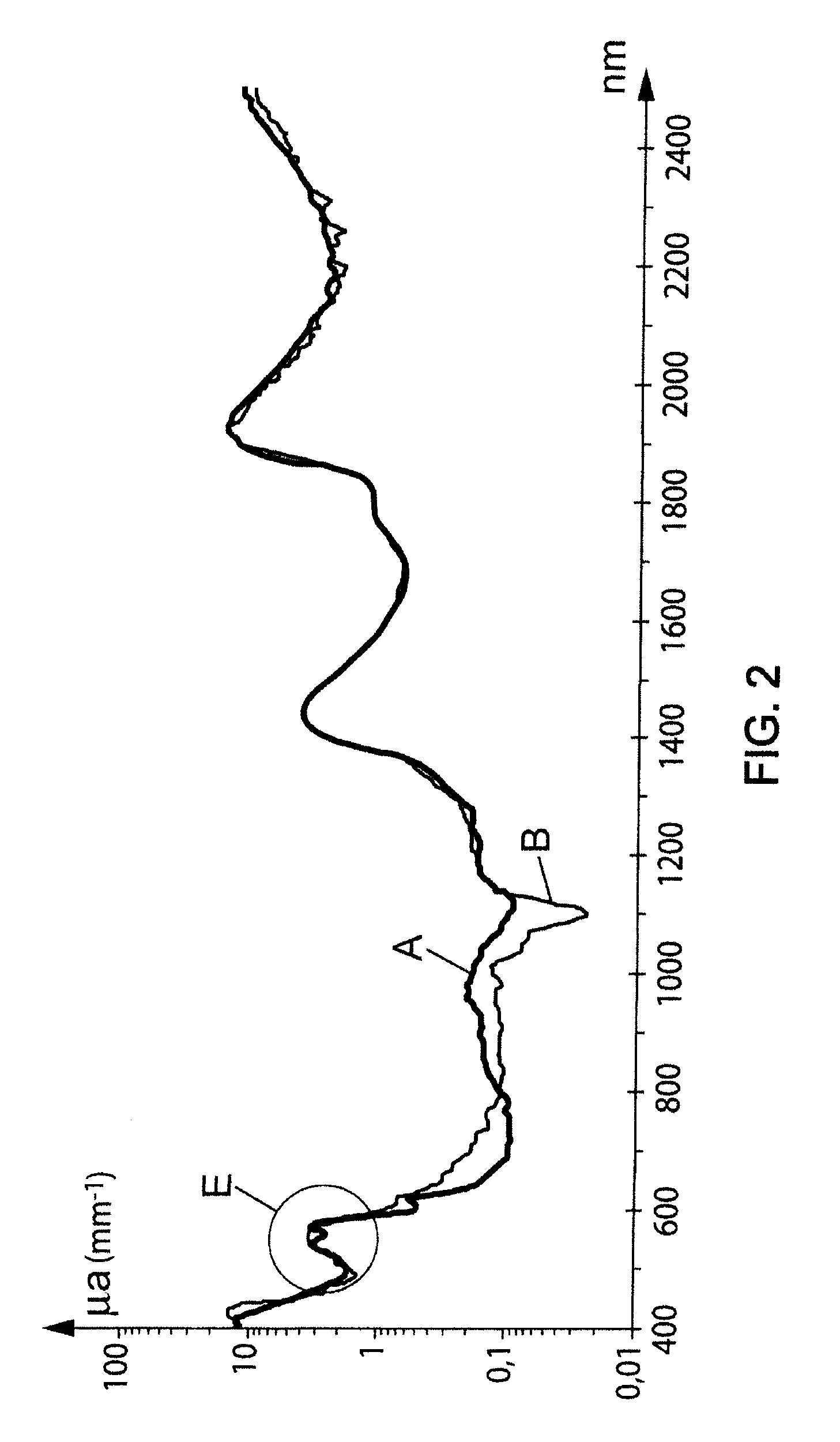
[0030]In FIG. 2, the curve A plotted as a thick line represents, according to the wavelength of an incident e...


PUM


Abstract

The invention relates to a method for validating a biometrical acquisition, mainly the acquisition of a body imprint of a body area such as fingerprints or a face imprint, wherein the method involves together with the biometric acquisition: lighting the body area using at least one radiation having at least two respective different wavelengths between approximately 500 nm and 1150 nm; taking at least two reflectometry measurements concerning said and at least two wavelengths for measuring the reflection index of the tissues for these wavelengths; calculating the ratio for two measured indices; and comparing the ratio with a range of reference values characterizing a haemoglobin-containing living tissue in terms of proportions of oxygenated and non-oxygenated forms characteristic of the living states for the wavelengths in question; if the ratio is included in said range, the body area is considered as living and the biometrical acquisition is validated; and conversely, if the body area is considered as not living, the biometrical acquisition cannot be validated.

Description

CROSS-REFERENCE TO RELATED APPLICATIONS[0001]This application is a U.S. national stage filing of International Patent Application No. PCT / FR2007 / 052243 filed on Oct. 25, 2007, which claims priority under the Paris Convention to French Patent Application No. 06 09378, filed on Oct. 25, 2006.FIELD OF THE DISCLOSURE[0002]The present invention relates generally to the field of biometric capture, in particular of body imprints of an area of the body, notably a fingerprint or face print, on an individual, for example in order to identify or authenticate an individual, and more specifically it relates to refinements made in this field.BACKGROUND OF THE DISCLOSURE[0003]Fraud when it comes to body print capture, notably, commonly, fingerprint capture, can, according to one of its aspects, consist of the so-called “false finger” technique: the defrauder uses a false finger (or a false area of the body) reproducing the body print characterizing an individual. This false finger can, for example...

Claims


Application Information

Patent Timeline
Patent Type & Authority Patents(United States)
IPC IPC(8): G06F7/04G06V10/143G06V30/144
CPCG06K9/2018G06K9/0012G06V40/1394G06V10/143A61B5/117G06V10/10G06F18/00
Inventor THIEBOT, ALAINFOURRE, JOEL-YANNLAMBERT, LAURENT
Owner IDEMIA IDENTITY & SECURITY FRANCE
Why Eureka
Try Eureka