Illuminating lens, lighting device, surface light source, and liquid-crystal display apparatus

a technology of liquid crystal display and illumination lens, which is applied in lighting and heating apparatus, instruments, condensers, etc., can solve the problems of large number of light emitting diodes and cost reduction obstacles, and achieve the effect of widening the range of transmission directions

Active Publication Date: 2013-08-13
SHENZHEN JUFEI OPTOELECTRONICS CO LTD
View PDF50 Cites 8 Cited by
  • Summary
  • Abstract
  • Description
  • Claims
  • Application Information

AI Technical Summary

Benefits of technology

[0009]It is an object of the present invention to provide an illuminating lens capable of further widening the range of transmission directions for light from a light source, and to provide a lighting device, a surface light source, and a liquid-crystal display apparatus each including this illuminating lens.
[0016]In the illuminating lens configured as described above, the most part of the light that has been emitted from the light source and reached the transmissive region located in the center of the first light exit surface is refracted at the transmissive region, and thus the area surrounding the optical axis of the lens on the surface to be irradiated is irradiated with the refracted light. On the other hand, the most part of the light that has been emitted from the light source and reached the total reflection region located on the outer peripheral side of the first light exit surface is totally reflected at the total reflection region. For example, in the case where a reflecting plate is disposed on the light entrance surface side of the illuminating lens, the area of the surface to be irradiated located away from the optical axis of the lens is irradiated with the totally reflected light at the end. Furthermore, the most part of the light that has been emitted from the light source and reached the second light exit surface is refracted at the second light exit surface, and thus the area of the surface to be irradiated located away from the optical axis of the lens is irradiated with the refracted light. Accordingly, the present invention makes it possible to obtain a wider range of transmission directions for light from the light source. Therefore, the outer diameter of the lens of the present invention may be smaller than that of a conventional lens having a concave for only refracting light.

Problems solved by technology

The use of a large number of light emitting diodes allows the entire surface of the backlight to have uniform brightness, but the need for such a large number of light emitting diodes is an obstacle to cost reduction.

Method used


Image

  • Illuminating lens, lighting device, surface light source, and liquid-crystal display apparatus
  • Illuminating lens, lighting device, surface light source, and liquid-crystal display apparatus
  • Illuminating lens, lighting device, surface light source, and liquid-crystal display apparatus

Examples


first embodiment

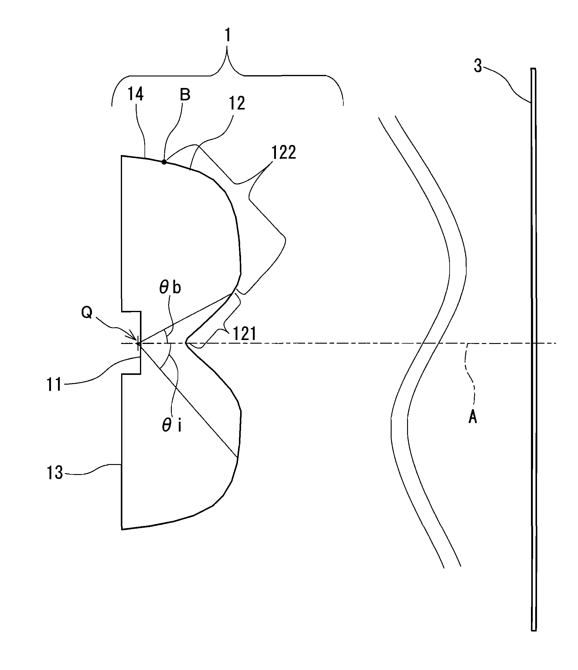
[0045]An illuminating lens according to the first embodiment of the present invention will be described with reference to the accompanying drawings. FIG. 1 is a schematic diagram of an illuminating lens 1 according to the first embodiment. The illuminating lens 1, which is disposed between a light source (not shown in FIG. 1) having directivity and a surface to be irradiated 3, spreads light emitted from the light source and emits the spread light to the surface to be irradiated 3. That is, the illuminating lens 1 widens the range of transmission directions for light from the light source. In the illuminance distribution on the surface to be irradiated 3, the illuminance is greatest on the optical axis A that is the design center line of the illuminating lens 1 and decreases almost monotonically toward the edge. The light source and the illuminating lens 1 are disposed so that their optical axes coincide with each other.

[0046]Specifically, the illuminating lens 1 has a light entranc...

second embodiment

[0071]FIG. 3 is a schematic diagram of a lighting device 7 according to a second embodiment of the present invention. This lighting device 7 includes a light emitting diode 2 for emitting light, and an illuminating lens 1 of the first embodiment for spreading light emitted from the light emitting diode 2 so that the surface to be irradiated 3 is irradiated with the spread light.

[0072]The light emitting diode 2 is in contact with the light entrance surface 11 of the illuminating lens 1 via a bonding agent, and connected optically to the light entrance surface 11. The light that has exited the illuminating lens 1 through the light exit surface 12 reaches the surface to be irradiated 3, and thus the surface to be irradiated 3 is illuminated with that light.

[0073]Light generation in the light emitting diode 2 has no directivity in itself, and a light emitting region has a refractive index of at least 2.0. When light from the light emitting region enters a low refractive region, the refr...

example 1

[0079]Table 1 below shows specific numerical values in Example 1.

[0080]

TABLE 1θisagY0.000.4850.760.4851.520.4872.260.4902.990.4943.700.4994.380.5055.050.5115.700.5176.330.5236.940.5307.530.5378.100.5448.650.5519.190.5589.710.56510.220.57210.710.58011.190.58711.650.59412.100.60212.540.60912.970.61613.380.62413.790.63114.180.63814.560.64514.940.65315.300.66015.660.66716.010.67516.350.68216.680.68917.000.69617.320.70317.630.71017.930.71718.230.72418.520.73118.810.73819.090.74519.370.75219.640.75919.900.76620.170.77320.420.77920.680.78620.920.79321.170.79921.410.80621.650.81321.880.81922.110.82522.340.83222.570.83822.790.84423.010.85023.230.85723.440.86323.660.86923.870.87524.080.88124.280.88624.490.89224.690.89824.890.90425.090.90925.290.91525.490.92025.680.92525.880.93126.070.93626.260.94126.450.94626.640.95126.830.95627.020.96127.210.96627.400.97127.590.97527.770.98027.960.98428.150.98928.330.99328.520.99728.701.00128.891.00529.071.00929.261.01329.451.01729.631.02129.821.02430.001.02...


PUM


Abstract

An illuminating lens has a light entrance surface and a light exit surface. The light exit surface has a first light exit surface recessed toward a point on an optical axis A and a second light exit surface extending outwardly from the periphery of the first light exit surface. The first light exit surface includes a transmissive region located in the center of the first light exit surface and a total reflection region located around the transmissive region. The transmissive region transmits light that has been emitted from a starting point Q, which is the position of a light source on the optical axis A, at a relatively small angle with respect to the optical axis A. The total reflection region totally reflects light that has been emitted from the starting point Q at a relatively large angle with respect to the optical axis A.

Description

BACKGROUND OF THE INVENTION[0001]1. Field of the Invention[0002]The present invention relates to an illuminating lens for widening a range of transmission directions for light from a light source such as a light emitting diode, and to a lighting device using this illuminating lens. The present invention further relates to a surface light source including a plurality of lighting devices, and to a liquid-crystal display apparatus in which this surface light source is disposed behind a liquid-crystal panel to serve as a backlight.[0003]2. Description of Related Art[0004]In a conventional backlight of a large-sized liquid-crystal display apparatus, a number of cold cathode tubes are disposed immediately below a liquid-crystal panel, and these cold cathode tubes are used with other members such as a diffusing plate and a reflecting plate. In recent years, light emitting diodes have been used as light sources for backlights. Light emitting diodes have increased their efficiency recently, ...

Claims


Application Information

Patent Timeline
Patent Type & Authority Patents(United States)
IPC IPC(8): G02F1/1335
CPCG02F1/133603G02F1/133611G02B19/0028G02B19/0061G02F1/133605G02F2001/133607H01L33/58G02F1/133607
Inventor IIYAMA, TOMOKOKIMURA, SYUNSUKEMATSUKI, DAIZABURO
Owner SHENZHEN JUFEI OPTOELECTRONICS CO LTD
Why Eureka
Try Eureka