Image recording method and apparatus

a recording method and image technology, applied in the direction of electrical equipment, power drive mechanisms, printing, etc., can solve the problems of reducing image quality, causing various problems, and defective recording elements, so as to effectively carry out compensation for defective recording elements, suppress excessive compensation between defective recording elements, and increase the range of response to defective recording effects

Active Publication Date: 2013-08-20
FUJIFILM CORP
View PDF14 Cites 12 Cited by
  • Summary
  • Abstract
  • Description
  • Claims
  • Application Information

AI Technical Summary

Benefits of technology

[0016]The present invention has been contrived in view of these circumstances, an object thereof being to provide an image recording method and an image recording apparatus, whereby desirable image recording can be achieved even in a case where a plurality of defective recording elements have occurred in mutually proximate positions.
[0018]According to this aspect, even if a plurality of defective recording elements occur in mutually proximate positions, the compensation is carried out using recording elements which are situated at the periphery of the defective recording elements in accordance with the defective recording element distance (the distance between the defective recording elements), and therefore excessive compensation between the defective recording elements is suppressed. Consequently, it is possible to effectively carry out compensation for defective recording, and the range of response to defective recording is increased.
[0029]According to this aspect, excessive compensation in recording positions between the defective recording elements is suppressed by making the tone value of the recording position corresponding to the recording element situated between the defective recording elements smaller than the tone value of the recording position corresponding to the recording element not situated between the defective recording elements.
[0043]According to the present invention, even if a plurality of defective recording elements occur in mutually proximate positions, compensation is carried out using recording elements which are situated at the periphery of the defective recording elements in accordance with the defective recording element distance (the distance between the defective recording elements), and therefore excessive compensation between the defective recording elements is suppressed. Consequently, it is possible to effectively carry out compensation for defective recording elements, and the range of response to defective recording is increased.

Problems solved by technology

In an inkjet recording apparatus, a defective recording element which does not have a normal ink ejection state gives rise to various problems.
In particular, in the single-pass image recording using a full-line head, stripe-shaped density non-uniformities or banding occur in the recorded image as a result of error in the recording characteristics, such as recording position error, ejected droplet error, ejection failure, and the like, which are caused by defective recording elements, and hence the image quality declines dramatically.
Implementing this technology places restrictions on the method used in the head and the range of correction.
In a recording head in which a large number of recording elements are arranged in a two-dimensional configuration, it is readily envisaged that defects may occur in a plurality of recording elements.
Moreover, there are cases where the plurality of defective recording elements are in close proximity to each other to the extent of affecting the appearance of recorded image as observed by the human eye.
In cases where a plurality of recording elements in mutual proximity have suffered abnormalities, if the above-described compensation for an isolated defective recording element is directly applied, then insufficient compensative functions are displayed and it may be impossible to obtain desired effects.

Method used


Image

  • Image recording method and apparatus
  • Image recording method and apparatus
  • Image recording method and apparatus

Examples


Embodiment Construction

Compensation for Defective Recording Elements

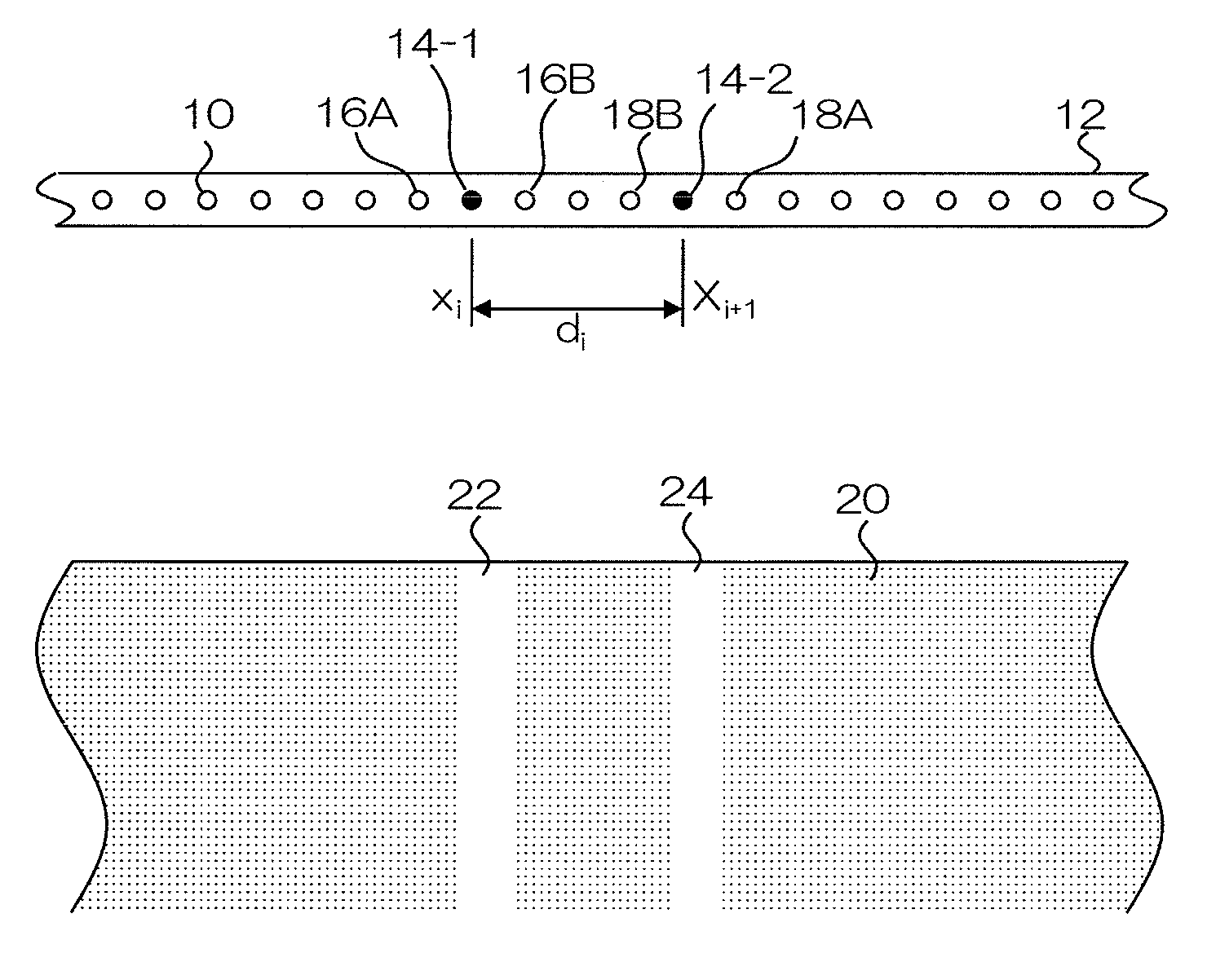
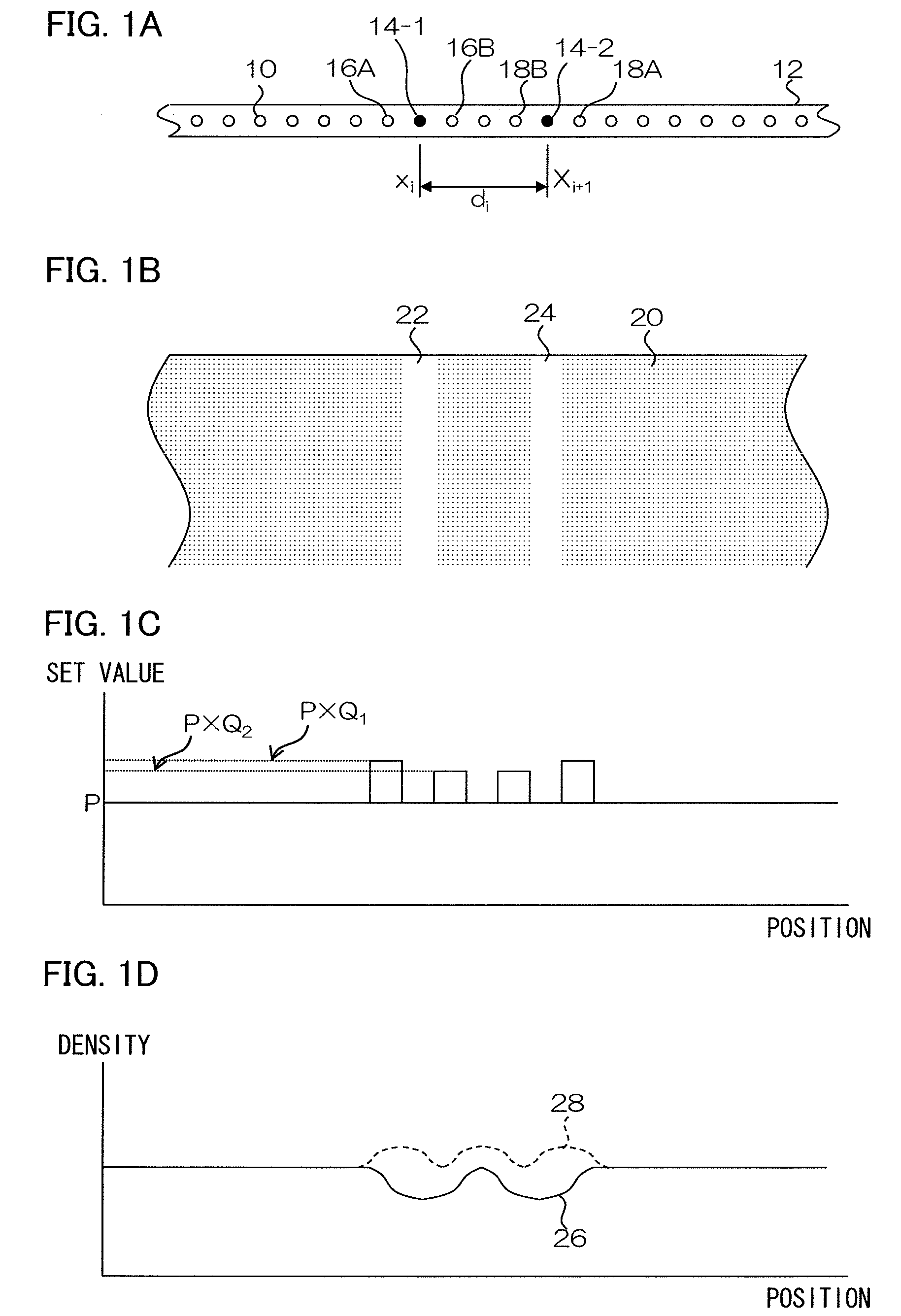
[0058]Firstly, compensation for defective recording elements in an image recording method according to an embodiment of the present invention is described.

[0059]FIGS. 1A to 1D show schematic views of the image recording method in an embodiment of the present embodiment.

[0060]FIG. 1A shows a schematic view of an inkjet head 12, which includes a plurality of nozzles (recording elements) 10. The inkjet head 12 shown in FIG. 1A has a structure in which N nozzles 10 are arranged (where N is an integer larger than 1) in one row at a prescribed arrangement pitch in a direction substantially perpendicular to the conveyance direction of the recording medium. Nozzles numbers 1 to N are assigned to the N nozzles. If there are n defective nozzles (where n is an integer from 1 to N), then the position of the i-th defective nozzle of the n defective nozzles is Xi (where i is an integer from 1 to n). In other words, Xi indicates each nozzle number from ...


PUM


Abstract

An image recording method of recording a desired image on a recording medium by a recording head having recording elements which form pixels on the recording medium, while moving at least one of the recording medium and the recording head relatively to each other in a prescribed conveyance direction, the method includes: a defective recording element information acquisition step of acquiring defective recording element information including position information of defective recording elements included in the recording elements; and a defective recording element compensation step of performing compensation for the defective recording elements by using compensation recording elements in accordance with a distance between a pair of the defective recording elements derived from the position information, the compensation recording elements being of normal recording elements included in the recording elements situated nearby the pair of the defective recording elements.

Description

BACKGROUND OF THE INVENTION[0001]1. Field of the Invention[0002]The present invention relates to an image recording method and an image recording apparatus, and more particularly, to image correction technology relating to defective recording elements in a recording head having a plurality of recording elements.[0003]2. Description of the Related Art[0004]An inkjet recording apparatus, which forms a desired image on a recording medium by an inkjet method, is an image recording apparatus widely used. The inkjet recording apparatus can include a full-line inkjet head having nozzles (recording elements) arranged in a two-dimensional configuration and achieve high productivity by means of single-pass image recording, which forms an image on the whole surface of paper by performing just one scanning action of the full-line head and the paper.[0005]In an inkjet recording apparatus, a defective recording element which does not have a normal ink ejection state gives rise to various problems...

Claims


Application Information

Patent Timeline
Patent Type & Authority Patents(United States)
IPC IPC(8): B41J29/393
CPCB41J29/393B41J2/2139B41J2/2146B41J2/2142H04N1/4015B41J2025/008
Inventor INOUE, YOSHIAKI
Owner FUJIFILM CORP
Why Eureka
Try Eureka