Optical device and projection-type image display apparatus

a technology of optical devices and projection-type images, applied in non-linear optics, lighting and heating devices, instruments, etc., can solve the problems of limited support portion of optical devices, spots prone to be scratched, etc., to reduce the risk of light-reflecting side surface scratches, reduce the effect of light-use efficiency and cost reduction

Inactive Publication Date: 2013-08-20
SANYO ELECTRIC CO LTD +1
View PDF17 Cites 0 Cited by
  • Summary
  • Abstract
  • Description
  • Claims
  • Application Information

AI Technical Summary

Benefits of technology

[0012]According to the aspect described above, since the optical device is made of transparent resin, costs can be lower than a tapered rod made of glass, and the like.
[0013]Moreover, since the supporting portion configured to support the main body of the optical device is provided on the light-reflecting side surface, when the optical device is placed on a flat surface, the light-reflecting side surface is not in contact with the flat surface. Specifically, spots prone to be scratched when handling the optical device are limited to the supporting portion. Thus, a possibility that the light-reflecting side surface will be scratched can be lowered. Consequently, reduction in light-use efficiency can be suppressed.

Problems solved by technology

Specifically, spots prone to be scratched when handling the optical device are limited to the supporting portion.

Method used


Image

  • Optical device and projection-type image display apparatus
  • Optical device and projection-type image display apparatus
  • Optical device and projection-type image display apparatus

Examples


first embodiment

(Projection-Type Image Display Apparatus)

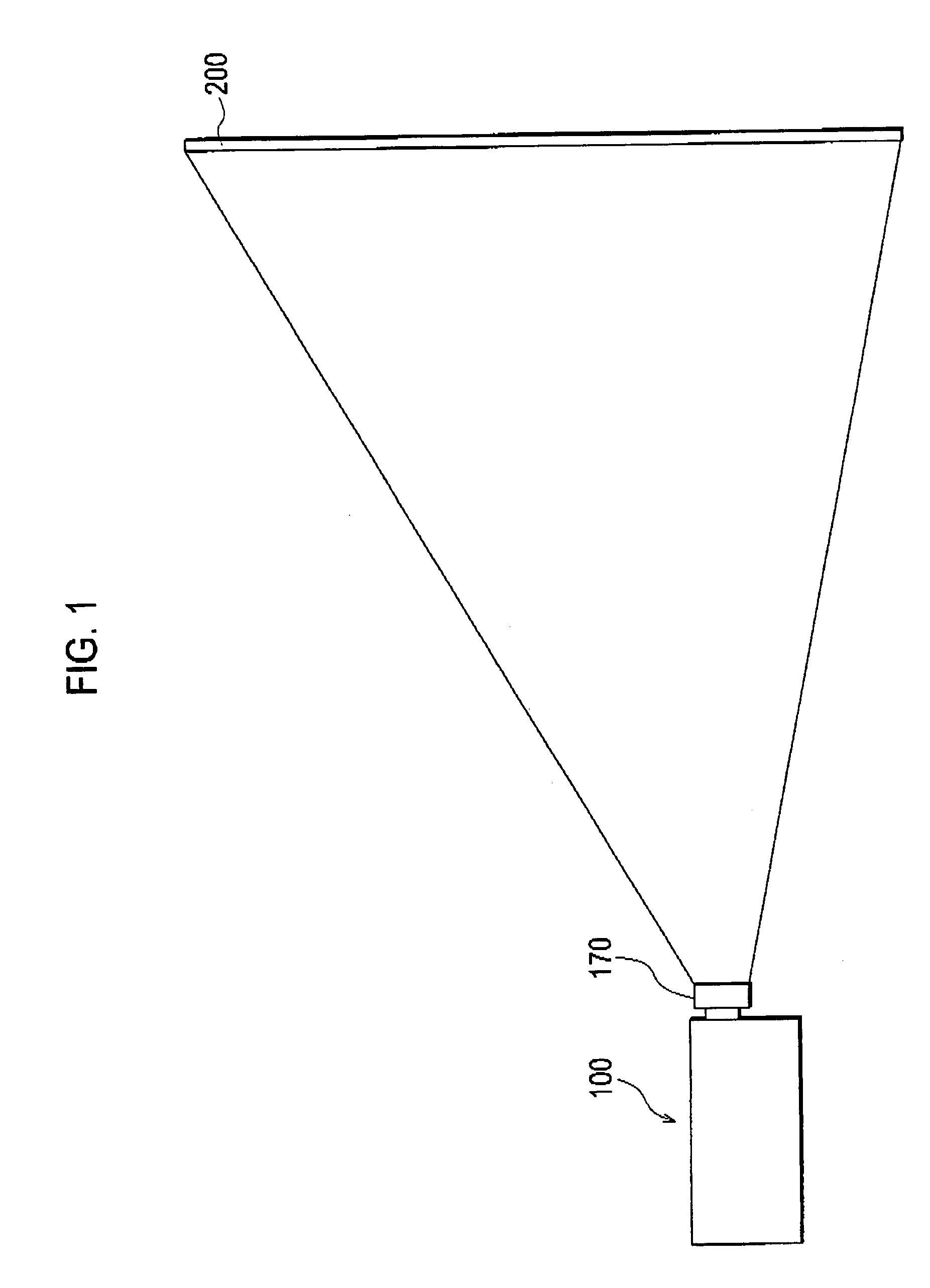
[0028]With reference to the drawings, description will be given below of a projection-type image display apparatus according to a first embodiment of the present invention. FIG. 1 is a view showing a projection-type image display apparatus 100 according to the first embodiment of the present invention.

[0029]As shown in FIG. 1, the projection-type image display apparatus 100 has a projection lens 170, and displays an image enlarged by the projection lens 170 on a screen 200.

[0030]Incidentally, in the first embodiment, description will be given on the assumption that the projection-type image display apparatus 100 is a three-panel-type projector.

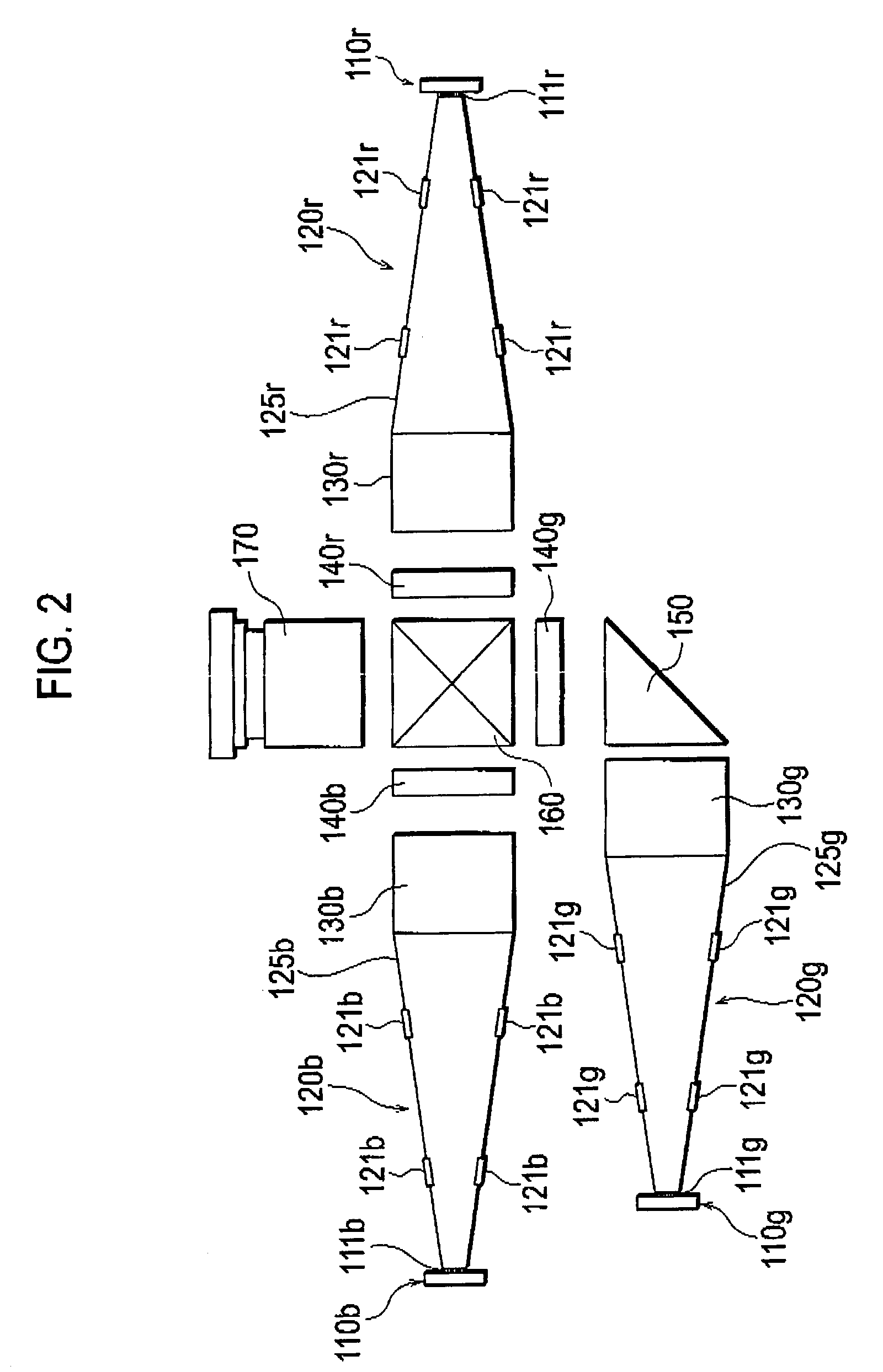
[0031]With reference to the drawings, a configuration of the projection-type image display apparatus will be described below. FIG. 2 is a view showing the configuration of the projection-type image display apparatus 100 according to the first embodiment of the present invention. Note that FIG. 2 shows o...

second embodiment

[0074]With reference to the drawings, description will be given below of an optical device (a tapered rod 120) according to a second embodiment of the present invention. Note that differences between the first embodiment described above and the second embodiment will be mainly described below.

[0075]Specifically, in the first embodiment described above, the main body 125 of the tapered rod 120 has the quadrangular tapered shape. On the other hand, in the second embodiment, a main body 125 of the tapered rod 120 has a cylindrical tapered shape.

[0076]FIG. 5 is a view showing the tapered rod 120 according to the second embodiment of the present invention. As shown in FIG. 5, the main body 125 of the tapered rod 120 has the cylindrical tapered shape, and is made of transparent resin. Here, as described above, the transparent resin is one having a refractive index larger than that of at least the air. The transparent resin includes acrylic resin such as PMMA (Poly Methyl Meth Acrylate), p...

examples

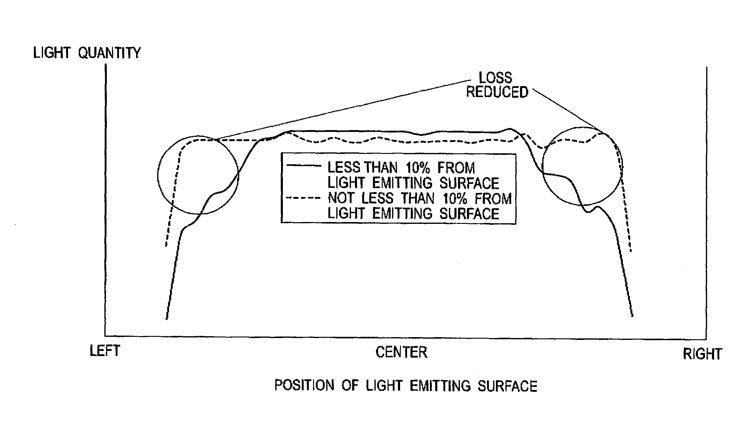
[0089]With reference to the drawings, an example of the present invention will be described below. FIG. 6 is a graph showing a relationship between a position of a supporting portion 121 on a light incident surface 122 side and a light-quantity loss in one example of the present invention. FIG. 7 is a graph showing a relationship between the position of the supporting portion 121 on a light emitting surface 123 side and a light quantity on a light emitting surface 123 in one example of the present invention.

[0090]To be more specific, as described in the first embodiment, a main body 125 of a tapered rod 120 was prepared. Here, the main body 125 has a quadrangular tapered shape. Also formed was the tapered rod 120 in which a length L1 from a light incident surface 122 to the supporting portion 121 is changed. Note that the supporting portions 121 were respectively provided on four ridge lines on which light-reflecting side surfaces 124 are in contact with each other.

[0091]First, the ...


PUM


Abstract

An optical device includes a main body having a light incident surface, a light emitting surface provided facing the light incident surface, and a light-reflecting side surface provided from a periphery of the light incident surface to a periphery of the light emitting surface. In the optical device, the light incident surface, the light emitting surface and the light-reflecting side surface are mirror-finished, and a supporting portion configured to support the main body is provided on the light-reflecting side surface.

Description

CROSS REFERENCE TO RELATED APPLICATIONS[0001]This application is based upon and claims the benefit of priority from prior Japanese Patent Application No. 2006-108960, filed on Apr. 11, 2006, and prior Japanese Patent Application No. 2007-103292, filed on Apr. 10, 2007; the entire contents of which are incorporated herein by reference.BACKGROUND OF THE INVENTION[0002]1. Field of the Invention[0003]The present invention relates to an optical device having a light incident surface, a light emitting surface and a light-reflecting side surface, all of which are mirror-finished, and a projection-type image display apparatus including the optical device.[0004]2. Description of the Related Art[0005]A projection-type image display apparatus including a light source, an optical modulation element (for example, a liquid crystal panel), a projection lens and the like has been generally well-known. Moreover, as such a projection-type image display apparatus, a projection-type image display appar...

Claims


Application Information

Patent Timeline
Patent Type & Authority Patents(United States)
IPC IPC(8): G03B21/28
CPCG02B27/0994H04N9/3152
Inventor IKEDA, TAKASHIYOKOTE, YOSHIHIROMATSUMOTO, SHINYASATO, KEIETSUTOMITE, KAZUTAKA
Owner SANYO ELECTRIC CO LTD
Why Eureka
Try Eureka