
Double shear material chopper

a material chopper and double shear technology, applied in the field of material chopping, can solve the problems of large drawbacks of the design of the chopper, the need for more power to operate, and the inability to provide a uniform cut length, etc., to achieve the effect of reducing power requirements, ensuring uniform cut length, and ensuring clean cutting of crop residu

Inactive Publication Date: 2013-08-20
IOWA STATE UNIV RES FOUND
View PDF64 Cites 3 Cited by
  • Summary
  • Abstract
  • Description
  • Claims
  • Application Information

AI Technical Summary

Benefits of technology

[0006]Therefore it is a primary object, feature, or advantage of the present invention to improve over the state of the art.
[0007]It is a further object, feature, or advantage of the present invention to provide a two axis crop residue chopper which may be used to cut crop residue for the purpose of harvesting biomass feed stock for conversion to ethanol or any other use.
[0008]It is a still further object, feature, or advantage of the present invention to provide a chopper that cuts crop residues on perpendicular planes.
[0009]Another object, feature, or advantage of the present invention is to provide more uniform cut length to chopped crop residue.
[0010]Yet another object, feature, or advantage of the present invention is to provide a chopper where the depth of cutting teeth control length of cut.
[0011]A further object, feature, or advantage of the present invention is to provide for cutting of material regardless of orientation of material at entrance to chopper.

Problems solved by technology

These types of chopper designs have major drawbacks.
In particular, the flail style choppers do not provide a uniform length of cut and they require more power to operate than a shear style chopper.
Slicer style choppers employ shear style cutting, but they do not have the ability to uniformly size material that is randomly oriented.
Therefore, problems remain.

Method used


Image

  • Double shear material chopper
  • Double shear material chopper
  • Double shear material chopper

Examples


Embodiment Construction

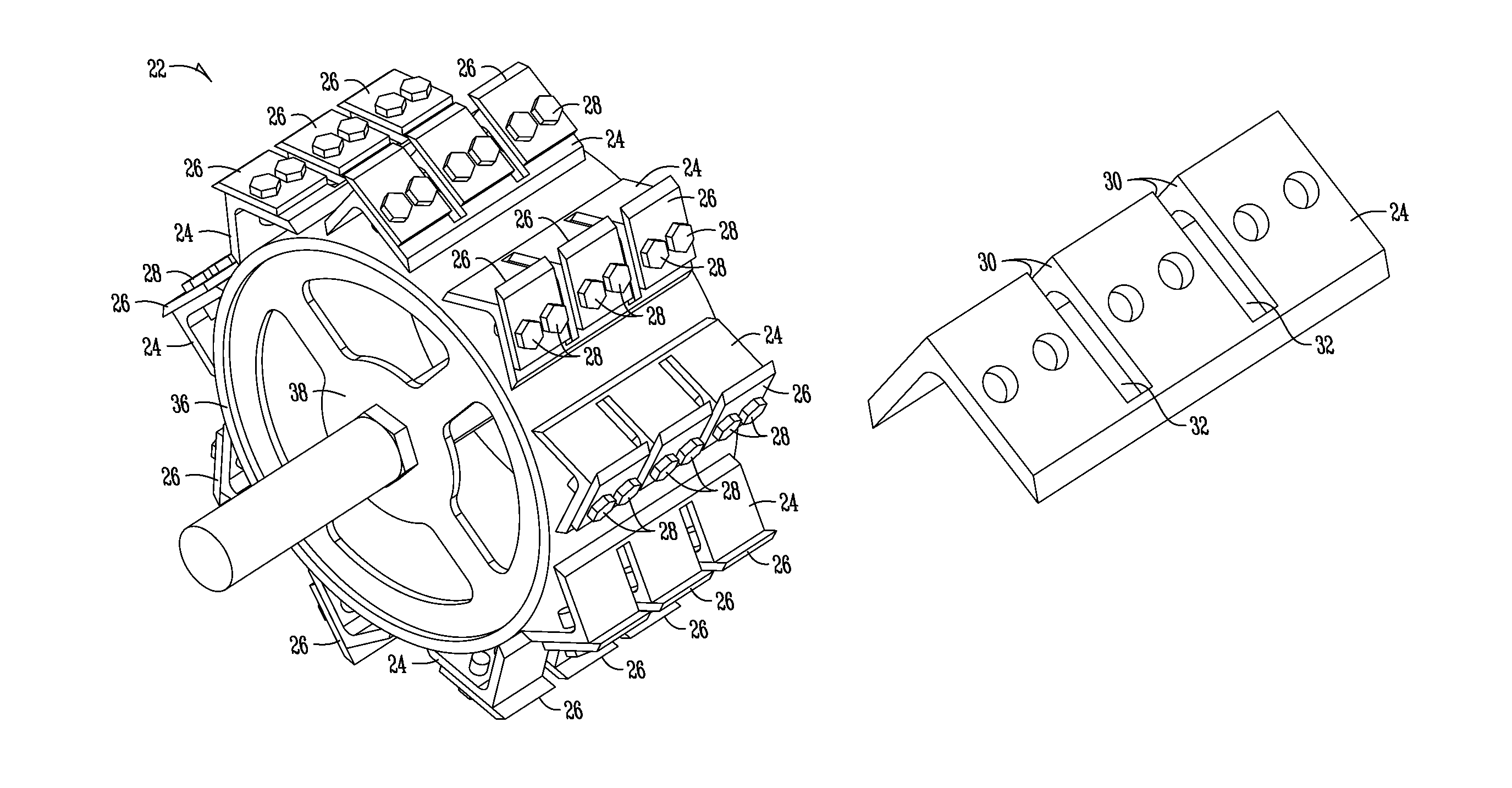
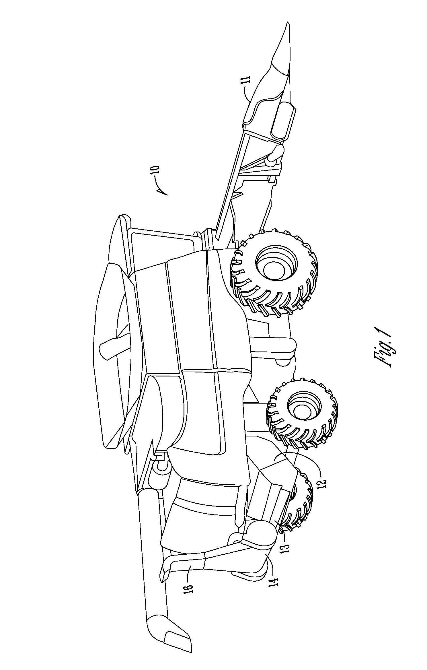
[0039]The double shear material chopper is a device designed to use shearing to reduce particle size of material fed through it. Its use is described with respect to reducing the particle size of corn stover being discharged from a combine harvester. It is to be appreciated that alternative uses exist including the chopping of any number of types of organic or inorganic material.

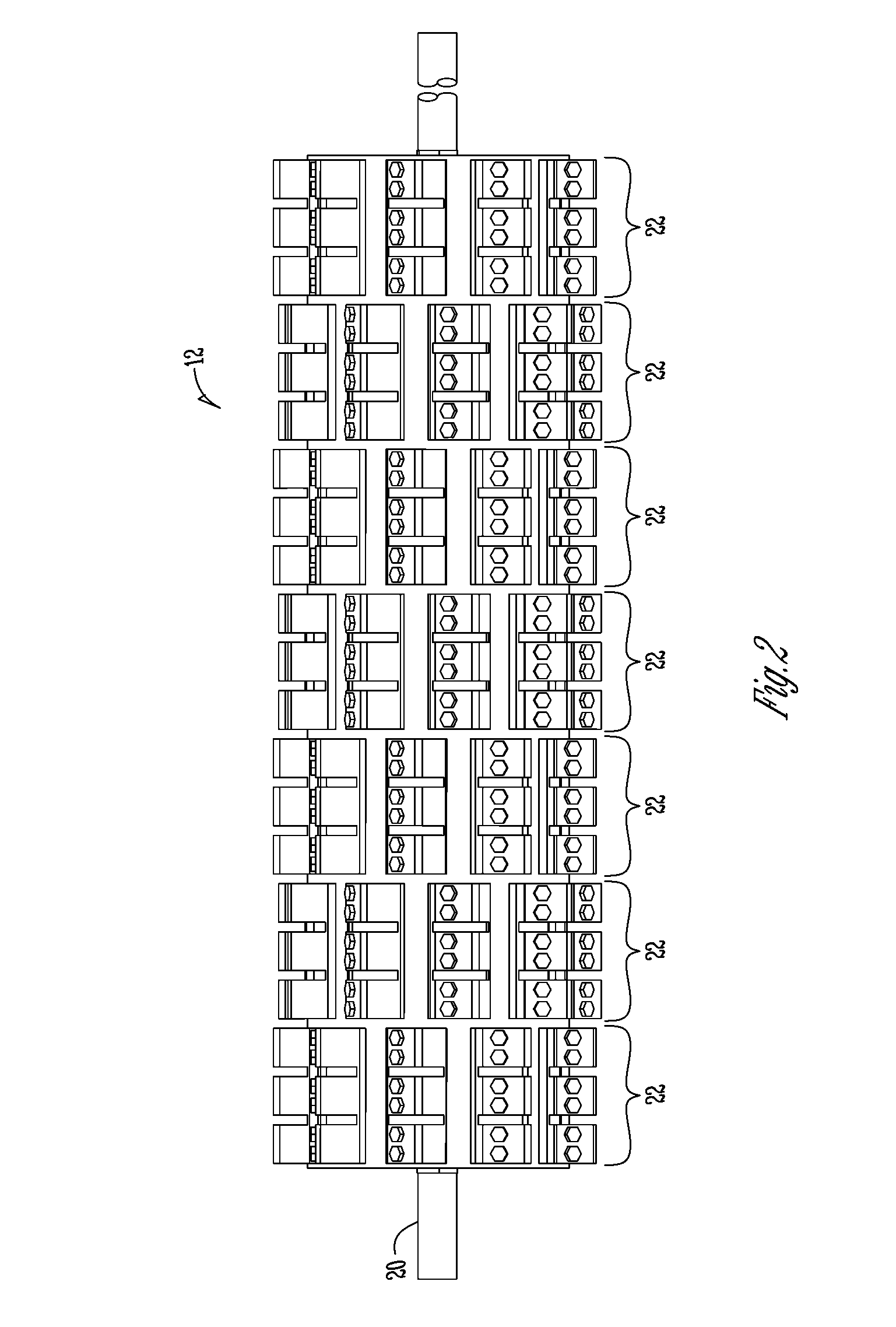
[0040]The double shear material chopper has two sets of blades oriented perpendicular to one another, and each set of blades has associated counter shear surfaces to simultaneously produce shearing action in two directions. The reason shearing in two directions is desirable is because it provides a means of uniformly sizing the material being chopped. Uniform sizing of material may be important in various applications. For example, uniform sizing of corn stover may be useful where the corn stover is further processed, such as for ethanol production. The double shear chopper reduces the particle size of the m...


PUM


Abstract

A material chopper may include a counter shear bar, a plurality of stationary knives associated with the counter shear bar, a shaft, at least one rotor section operatively connected to the shaft, each of the at least one rotor section configured to rotate with the shaft, at least one knife holder in each of the at least one rotor section, at least one knife operatively connected to each of the at least one knife holder, and slots in each of the at least one knife holder, wherein edges of the slot provide counter shear surfaces for the plurality of stationary knives. The material chopper may be added to or incorporated into a harvesting machine such as a combine.

Description

CROSS-REFERENCE TO RELATED APPLICATIONS[0001]This application claims priority under 35 U.S.C. §119 to provisional application Ser. No. 60 / 910,244 filed Apr. 5, 2007, herein incorporated by reference in its entirety.GRANT REFERENCE[0002]This invention was made with government support under Grant No. 68-3A75-4-137 awarded by USDA / NRCS and DOE. The Government has certain rights in this invention.BACKGROUND OF THE INVENTION[0003]The present invention relates generally to material chopping. To assist in providing a background of the invention problems associated with choppers used to produce stover are discussed. It is to be understood, however, that the present invention is not to be limited to this specific application.[0004]Recently, increased interest has been placed on a stover. The term “stover” is generally the stalk and leaf materials of a crop without the harvested grain. Sometimes this is referred to as crop residue which is indicative of the relative value of stover compared t...

Claims


Application Information

Patent Timeline
Patent Type & Authority Patents(United States)
IPC IPC(8): A01F12/40
CPCA01F29/02A01F12/40
Inventor BIRRELL, STUART J.SCHLESSER, BENJAMIN J.DILTS, MARK D.
Owner IOWA STATE UNIV RES FOUND
Learn More