Complex wire formed devices

a wire-forming device and complex technology, applied in the field of complex wire-forming devices, can solve the problems of limited device constraint ability, lack of oxygen and nutrients to brain tissue, limited access to remote regions by doctors, etc., and achieve the effect of shortening the length of the main bundl

Inactive Publication Date: 2013-08-20
TYCO HEALTHCARE GRP LP
View PDF251 Cites 60 Cited by
  • Summary
  • Abstract
  • Description
  • Claims
  • Application Information

AI Technical Summary

Benefits of technology

[0012]The devices of the present invention typically include a main bundle from which the wires extend. In most case, the main bundle extends for a length sufficient to withdraw the device from a body of a patient. Accordingly in such cases, the main bundle shall extend through the length of a catheter. In alternate constructions, the main bundle may be affixed to a single wire or member. In such cases, the single wire or member is used to manipulate the device, which allows shortening of the length of the main bundle.
[0016]As noted herein, the joint-less construction improves the flexibility and strength of the device by eliminating joints, connection points, or other attachment points. In addition, the joint-less construction improves the ability of the device to be delivered through a small microcatheter. As a result, the device and microcatheter are able to access remote regions of the vasculature.
[0018]When used in the vasculature to retrieve obstructions, the devices may include a low friction mode (such as a set of parallel wires, or wires extending axially along the lumen or vessel) that converts to an increased friction mode (such as a compressed set of wires acting on the obstruction or a twisted set of wires acting on the obstruction). The increase in friction is an increase in the friction between the obstruction and the device (as opposed to the vessel wall. In some cases, the low friction mode is a low surface area mode and the high friction mode is a high surface area mode. When configured in the low friction mode, the device is better suited to engage the obstruction without the undesirable effect of prematurely mobilizing the obstruction or compacting the obstruction (e.g., when wires are slid across the obstruction in a transverse motion). Upon engaging the obstruction, the device will conform to a high friction mode with respect to the obstruction (in some cases the device will have an increased surface area mode). This high friction mode permits the device to better grip the obstruction for ultimate removal of the obstruction.
[0023]It should be noted that in some variations of the invention, all or some of the device can be designed to increase their ability to adhere to the obstruction. For example, the wires may be coupled to an energy source (e.g., RF, ultrasonic, or thermal energy) to “weld” to the obstruction. Application of energy to the device can allow the surrounding portion to deform into the obstruction and “embed” within the obstruction. Alternatively, the device can impart a positive charge to the obstruction to partially liquefy the obstruction sufficiently to allow for easier removal. In another variation, a negative charge could be applied to further build thrombus and nest the device for better pulling force. The wires can be made stickier by use of a hydrophilic substance(s), or by chemicals that would generate a chemical bond to the surface of the obstruction. Alternatively, the filaments may reduce the temperature of the obstruction to congeal or adhere to the obstruction.

Problems solved by technology

In addition, the degree to which a physician is limited in accessing remote regions of the cerebral vasculature is directly related to the limited ability of the device to constrain into a reduced profile for delivery.
Left untreated, the blockage causes a lack of supply of oxygen and nutrients to the brain tissue.
Blockages that interfere with this supply eventually cause the brain tissue to stop functioning.
If the disruption in supply occurs for a sufficient amount of time, the continued lack of nutrients and oxygen causes irreversible cell death (infarction).
Regardless of the area where the device is to be used, when fabricating such a device the joints between adjacent shapes or sections of the device often impede the ability of the device to assume a sufficiently reduced profile or interfere with the geometry / stiffness of the device causing problems when navigating the device through the body.
Also, joints lead to potential failure locations, and may lead to fractured and embolized components within the body.

Method used


Image

  • Complex wire formed devices
  • Complex wire formed devices
  • Complex wire formed devices

Examples


Embodiment Construction

[0041]It is understood that the examples below discuss uses in the cerebral vasculature (namely the arteries). However, unless specifically noted, variations of the device and method are not limited to use in the cerebral vasculature. Instead, the invention may have applicability in various parts of the body. Moreover, the invention may be used in various procedures where the benefits of the method and / or device are desired.

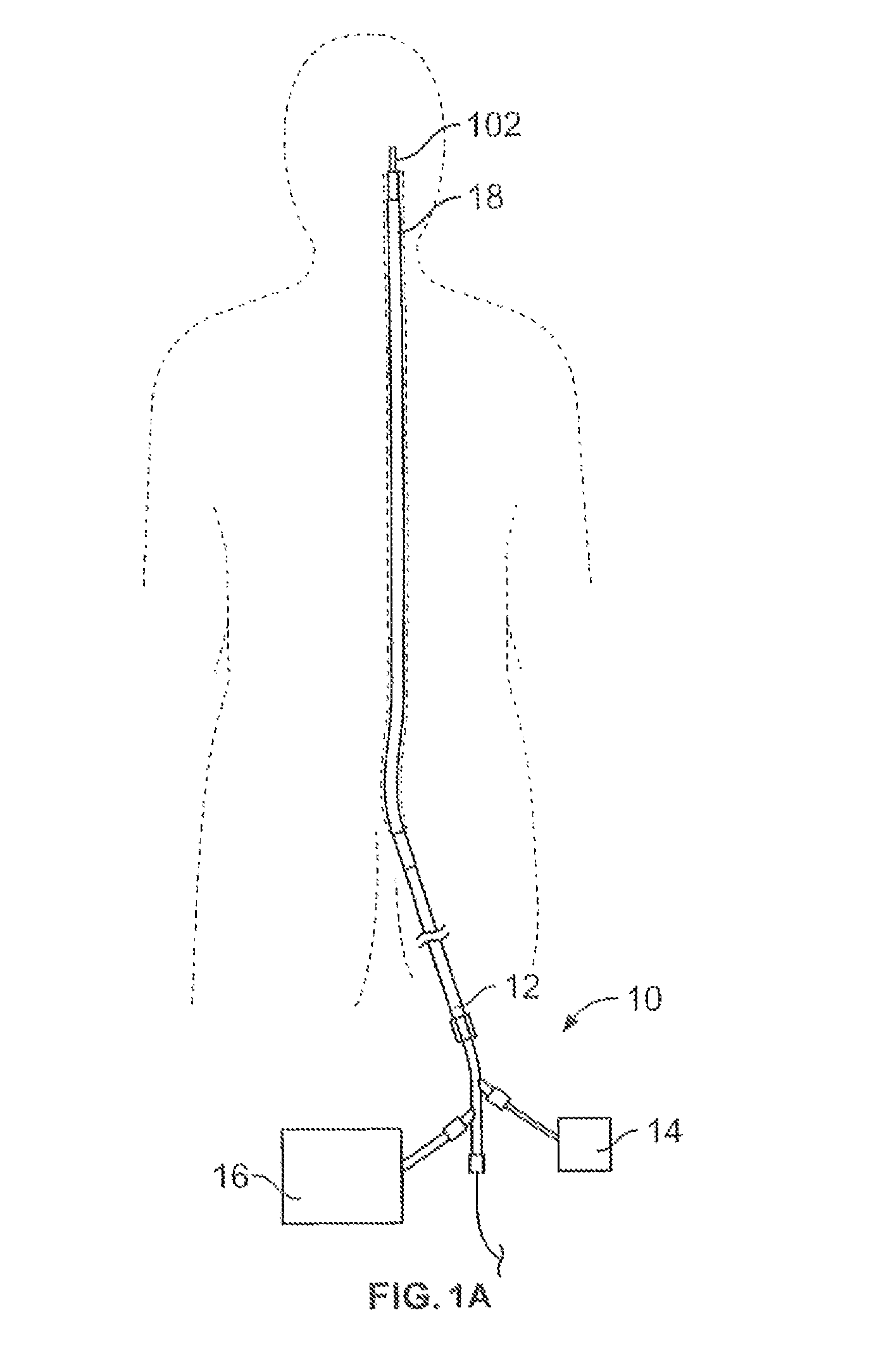
[0042]FIG. 1A illustrates a system 10 for removing obstructions from body lumens as described herein. In the illustrated example, this variation of the system 10 is suited for removal of an obstruction in the cerebral vasculature. Typically, the system 10 includes a catheter 12 microcatheter, sheath, guide-catheter, or simple tube / sheath configuration for delivery of the obstruction removal device to the target anatomy. The catheter should be sufficient to deliver the device as discussed below. The catheter 12 may optionally include an inflatable balloon 18 for t...


PUM


Abstract

The devices and methods described herein relate to jointless construction of complex structures. Such devices have applicability in through-out the body, including clearing of blockages within body lumens, such as the vasculature, by addressing the frictional resistance on the obstruction prior to attempting to translate and / or mobilize the obstruction within the body lumen.

Description

FIELD OF THE INVENTION[0001]The devices described herein are constructed in wire form where the wires diverge from a main bundle to form a variety of shapes that form a composite device. The benefit of such a diverging wire construction is that the composite complex device can be of a “joint-less” construction. Such devices have applicability in through-out the body, including clearing of blockages within body lumens, such as the vasculature, by addressing the frictional resistance on the obstruction prior to attempting to translate and / or mobilize the obstruction within the body lumen.BACKGROUND OF THE INVENTION[0002]Many medical device applications require advancement of device in a reduced profile to a remote site within the body, where on reaching a target site, the device assumes or is deployed into a relatively larger profile. Applications in the cerebral vasculature are one such example of medical procedures where a catheter advances from a remote part of the body (typically ...

Claims


Application Information

Patent Timeline
Patent Type & Authority Patents(United States)
IPC IPC(8): A61B17/221
CPCA61B17/221A61B17/32056A61B2017/00867A61B2017/2212A61B2017/2217A61F2/013A61B2017/2215
Inventor MARTIN, BRIAN B.
Owner TYCO HEALTHCARE GRP LP
Why Eureka
Try Eureka