Hardware device to physical structure binding and authentication

a physical structure and hardware technology, applied in the field of trusted computing, can solve the problems of high cost, inability to trustworthy computing (with software), and inability to protect unauthorized memory, etc., and achieve the effect of preventing subversive attacks on information processing hardware using physical system protection schemes that are difficult to achieve and expensiv

Active Publication Date: 2013-08-20
NAT TECH & ENG SOLUTIONS OF SANDIA LLC
View PDF19 Cites 199 Cited by
  • Summary
  • Abstract
  • Description
  • Claims
  • Application Information

AI Technical Summary

Problems solved by technology

Trustworthy computing (with software) cannot exist without trustworthy hardware to build it on.
Without detection of subversion by wholesale component substitution, today's information processing systems are vulnerable to sophisticated adversaries that can fabricate “look-alike” components that perform the same function as the intended component but which may contain additional subversion artifices that can be later triggered by an adversary to disrupt or compromise operation.
Using physical system protection schemes to prevent subversive attacks in deployed information processing hardware is technically difficult and expensive.
PUFs are derived from the inherently random, physical characteristics of the material, component, or system from which they are sourced, which makes the output of a PUF physically or computationally very difficult to predict.
Trusted foundry processing of silicon-based microelectronics requires enormous investments to protect against subversion; however, this investment imparts trust only during the fabrication phase of a component's life cycle.
Without the equivalent of rigorous two-person control of the component during the deployment phase of its life cycle, it can be difficult to demonstrate authenticity even for components from today's trusted foundries.

Method used


Image

  • Hardware device to physical structure binding and authentication
  • Hardware device to physical structure binding and authentication
  • Hardware device to physical structure binding and authentication

Examples


Embodiment Construction

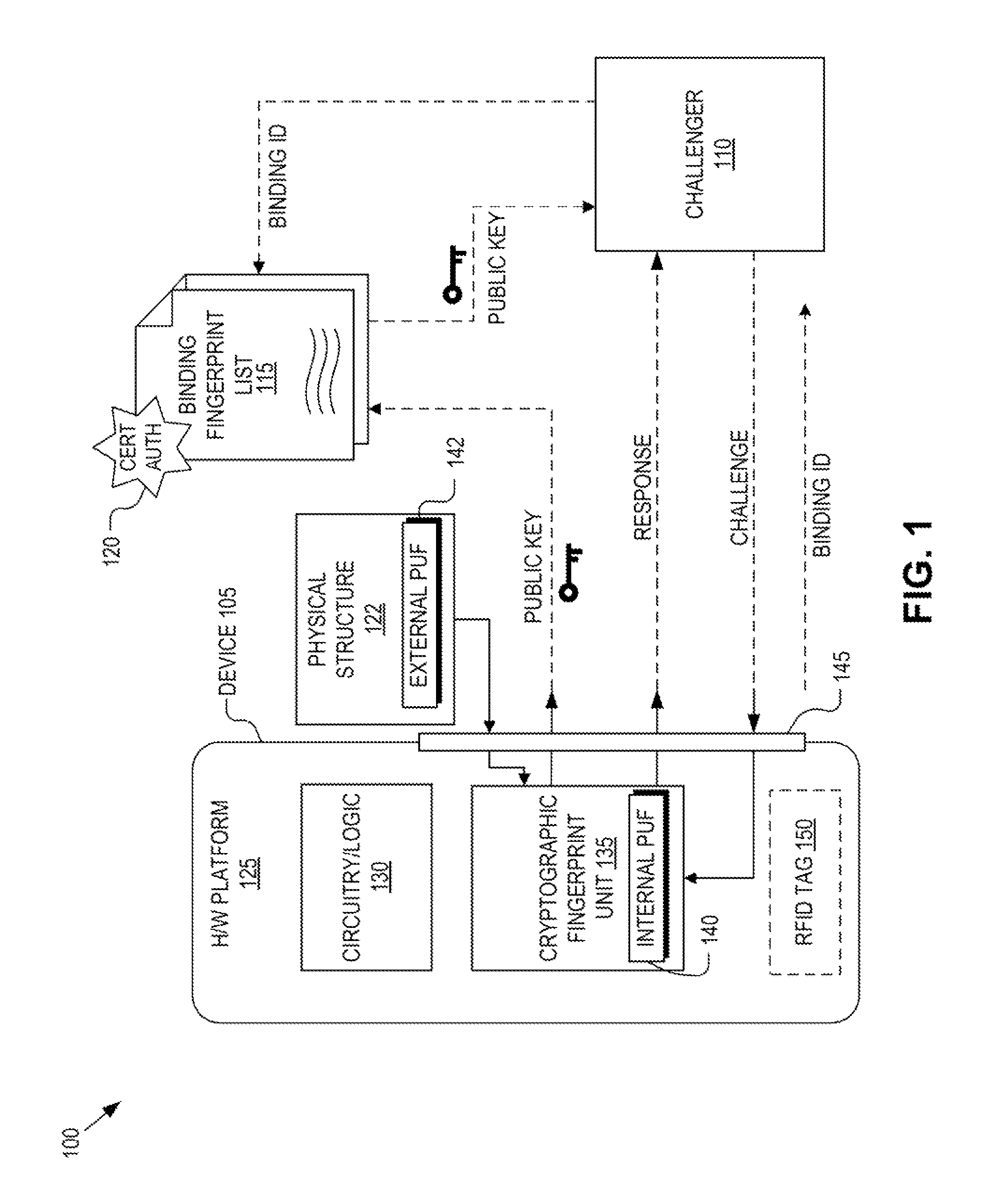
[0022]Embodiments of a system and method for authenticating bindings of hardware devices and physical structures to detect and deter device tampering and subversion by substitution are described herein. In the following description numerous specific details are set forth to provide a thorough understanding of the embodiments. One skilled in the relevant art will recognize, however, that the techniques described herein can be practiced without one or more of the specific details, or with other methods, components, materials, etc. in other instances, well-known structures, materials, or operations are not shown or described in detail to avoid obscuring certain aspects.

[0023]Reference throughout this specification to “one embodiment” or “an embodiment” means that a particular feature, structure, or characteristic described in connection with the embodiment is included in at least one embodiment of the present invention. Thus, the appearances of the phrases “in one embodiment” or “in an...


PUM


Abstract

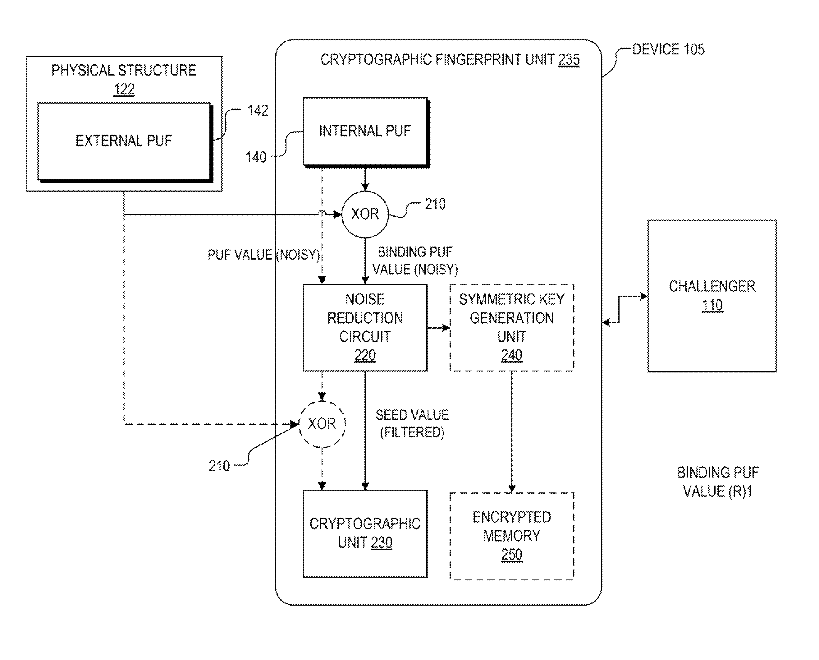
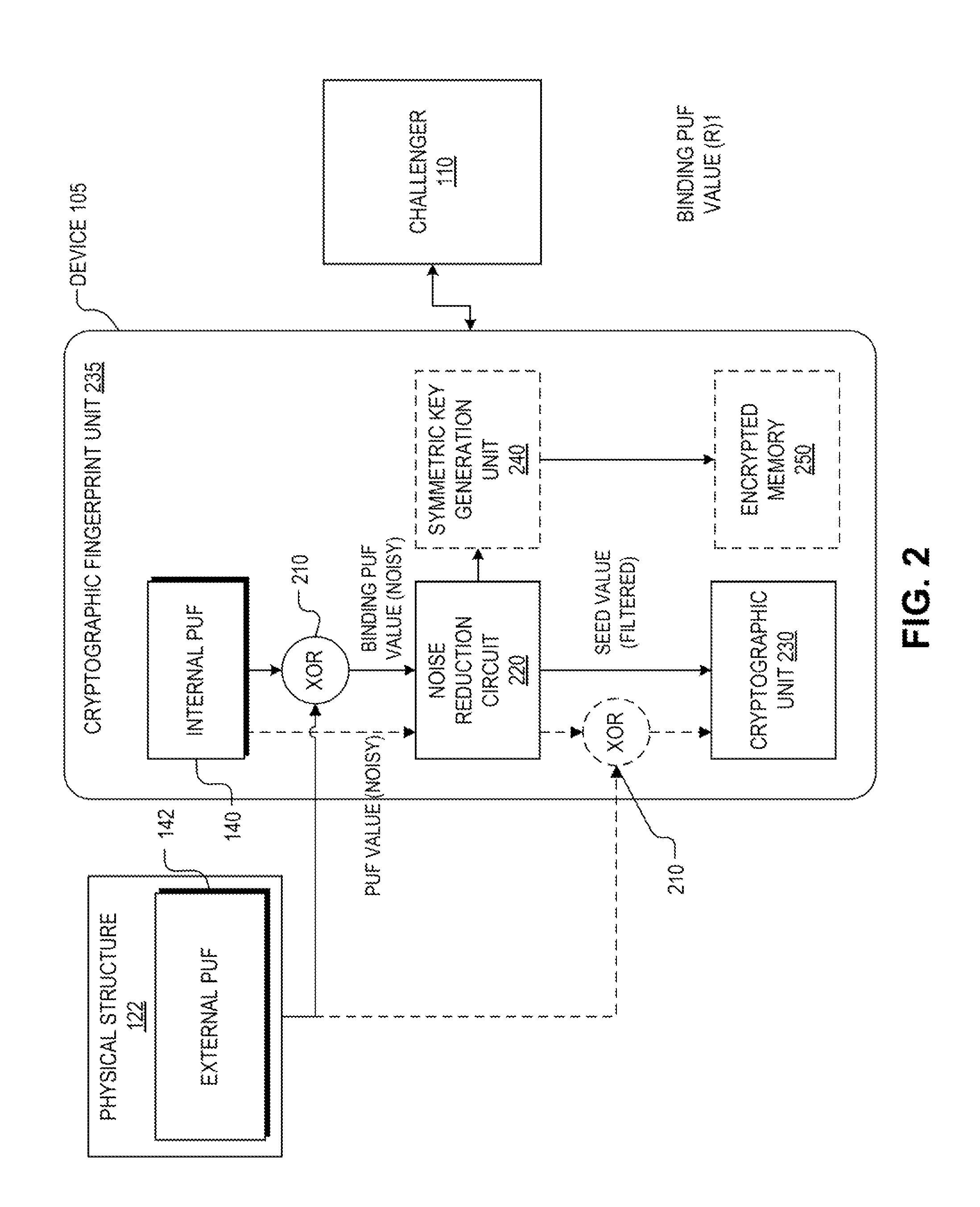
Detection and deterrence of device tampering and subversion may be achieved by including a cryptographic fingerprint unit within a hardware device for authenticating a binding of the hardware device and a physical structure. The cryptographic fingerprint unit includes an internal physically unclonable function (“PUF”) circuit disposed in or on the hardware device, which generate an internal PUF value. Binding logic is coupled to receive the internal PUF value, as well as an external PUF value associated with the physical structure, and generates a binding PUF value, which represents the binding of the hardware device and the physical structure. The cryptographic fingerprint unit also includes a cryptographic unit that uses the binding PUF value to allow a challenger to authenticate the binding.

Description

RELATED APPLICATIONS[0001]This application is a continuation-in-part of U.S. patent application Ser. No. 12 / 844,860, entitled “Deterrence of Device Counterfeiting, Cloning, and Subversion by Substitution Using Hardware Fingerprinting,” filed Jul. 27, 2010, the contents of which are hereby incorporated by reference.STATEMENT REGARDING FEDERALLY SPONSORED RESEARCH[0002]This invention was developed with Government support under Contract No. DE-AC04-94AL85000 between Sandia Corporation and the U.S. Department of Energy. The U.S. Government has certain rights in this invention.TECHNICAL FIELD[0003]This disclosure relates generally to trusted computing, and in particular but not exclusively, relates to binding authentication to protect against tampering and subversion by substitution.BACKGROUND INFORMATION[0004]Trustworthy computing (with software) cannot exist without trustworthy hardware to build it on. Even if an integrated circuit is produced using rigorous procedures in a “Trusted Fo...

Claims


Application Information

Patent Timeline
Patent Type & Authority Patents(United States)
IPC IPC(8): G06F21/00
CPCG06F21/00G06F21/445H04L9/3278G06F2221/2115
Inventor HAMLET, JASON R.STEIN, DAVID J.BAUER, TODD M.
Owner NAT TECH & ENG SOLUTIONS OF SANDIA LLC
Why Eureka
Try Eureka