Crimping pliers

a technology of crimping pliers and pliers, which is applied in the direction of pliers, multi-purpose tools, cable installation apparatus, etc., can solve the problems of cutting the insulation of the cable, and achieve the effect of simple assembly process and simple but efficient design of the crimping pliers

Inactive Publication Date: 2013-08-27
WEZAG - WERKZEUGFAB
View PDF41 Cites 16 Cited by
  • Summary
  • Abstract
  • Description
  • Claims
  • Application Information

AI Technical Summary

Benefits of technology

[0018]According to the invention, it is not necessary to couple the second tool with both hand levers by suitable mounting or holding devices. Instead it is sufficient to mount the second tool with the first hand lever only, whereas the contact between the second tool and the second hand lever is solely built by the contact surfaces. This leads to a very simple but efficient design of the crimping pliers and a simple assembly process.
[0019]For crimping pliers described in the prior art section, the stroke of the first and the second tool necessarily correlate with each other and with the stroke of the hand levers. This leads to very narrow boundary conditions for the kinematics for the transfer mechanism between the hand levers and the crimping jaws on the one hand side and between the hand levers and the second tool on the other hand side. The inventive design with the second tool being solely held at the first hand lever and contacting the second hand lever during the full stroke of the hand levers or only during a part of the stroke of the hand levers increases the options for designing the kinematics and force transfer for the first and second tool.
[0028]According to another embodiment of the invention, the second tool might be rested or locked at least in one operating state. This rested or locked operating state might be the open operating state and / or closed operating state. This design in particular avoids undesired movements of the second tool in opening or closing direction when using the first tool for crimping a workpiece.

Problems solved by technology

In the small final partial stroke of the hand lever, the hand lever moves the stem and the seat with the result that the cutting element cuts into the insulation of the cable.

Method used


Image

  • Crimping pliers
  • Crimping pliers
  • Crimping pliers

Examples


Embodiment Construction

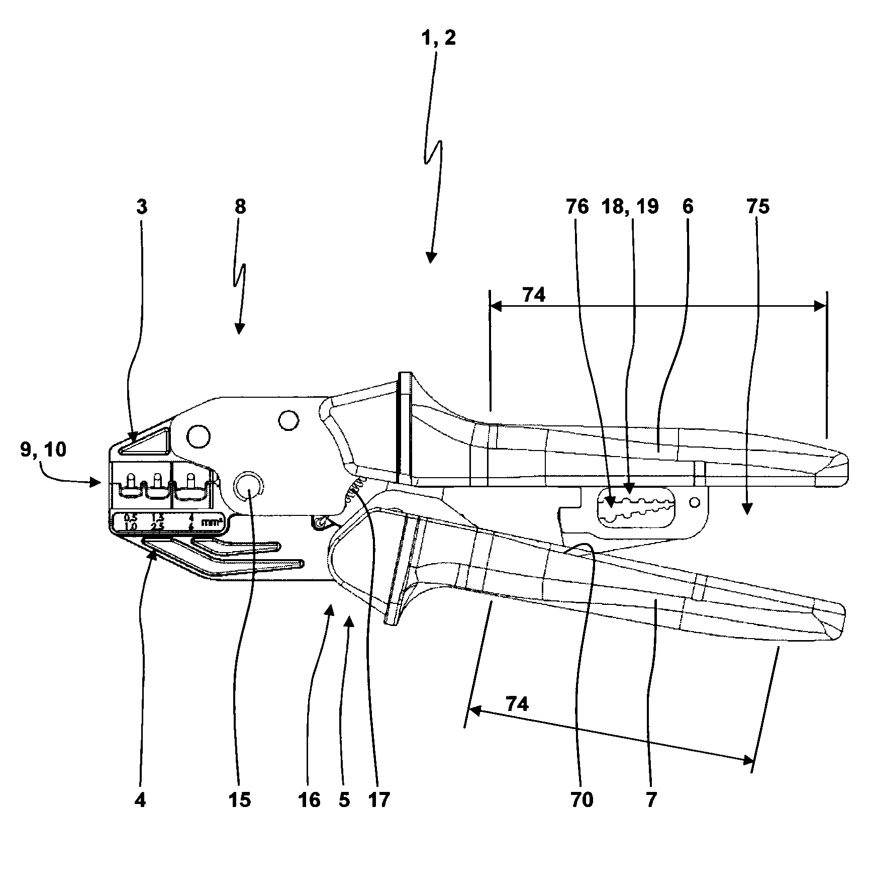
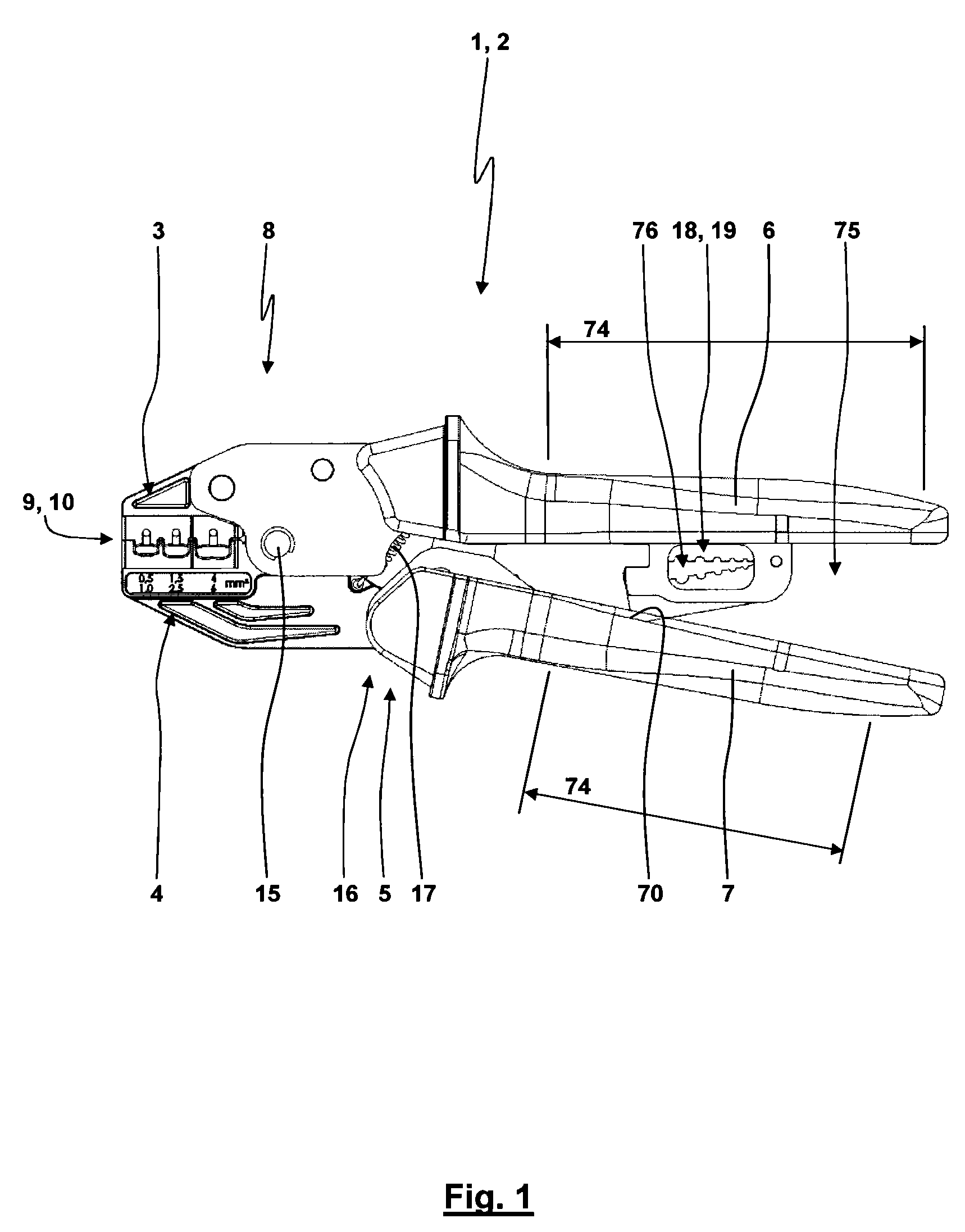
[0039]Referring now in greater detail to the drawings, FIG. 1 illustrates crimping pliers 2. The pliers 2 comprise crimping jaws 3, 4. The crimping jaws 3, 4 are linked by a transfer or transmission mechanism 5 with hand levers 6, 7 such that an opening or closing movement of the hand levers 6, 7 with manually applied opening or closing forces correlate with an opening or closing movement or stroke of the crimping jaws 3, 4 with related crimping forces at the crimping jaws 3, 4. A first tool 9 located at a head 8 of the crimping pliers 2 is built with the crimping jaws 3, 4. For the shown embodiment, in the first tool 9 the crimping jaws 3, 4 support nest bodies or crimping nest inserts each building three crimping nest halves. The different crimping nest halves are adapted and contoured for crimping plugs, fittings and the like having different diameters and / or geometries.

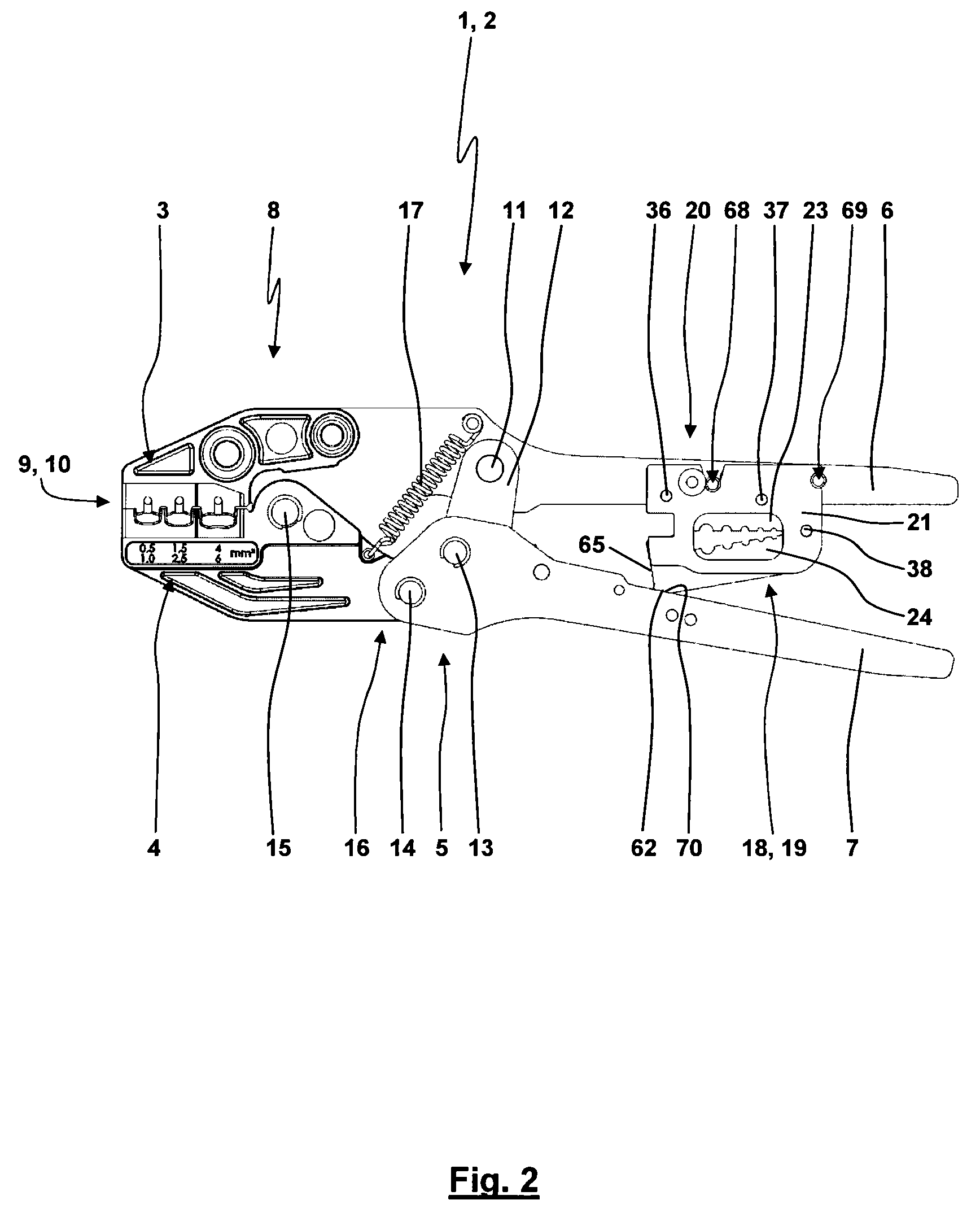
[0040]For the shown embodiment, the transfer mechanism 5 is built with a pliers part integrally building both t...


PUM

PropertyMeasurementUnit
diametersaaaaaaaaaa
forcesaaaaaaaaaa
opening angleaaaaaaaaaa

Abstract

The present invention relates to crimping pliers for crimping a workpiece. The crimping pliers comprise two hand levers. At the crimping pliers a first tool builds a crimping tool and comprises two crimping jaws located at a head of the pliers. The crimping jaws are linked by a transfer mechanism with the two hand levers. The invention suggests providing a second tool. The second tool comprises a working area, wherein the working area is located between the two hand levers. The second tool is solely mounted with a first hand lever of the two hand levers. The second hand lever comprises a contact surface cooperating with a contact surface of the second tool. The contact of the two contact surfaces is used for transferring an activating force from the hand levers to the second tool.

Description

CROSS REFERENCE TO RELATED APPLICATIONS[0001]This application claims priority to co-pending German Patent Application No. EP 09 171 826.2 entitled “Zange”, filed Sep. 30, 2009.FIELD OF THE INVENTION[0002]The present invention generally relates to crimping pliers building a tool for crimping a workpiece at a head of the crimping pliers, wherein the tool is activated by hand levers.BACKGROUND OF THE INVENTION[0003]German Utility Model DE 201 00 031 U1 discloses crimping pliers. The workpiece crimped with these crimping pliers is a cable connector crimped with an end of a cable. The tool of these crimping pliers used for the crimping process is built with two crimping die inserts being mounted with crimping jaws located at the head of the pliers. The crimping jaws are linked for being pivoted with an actuation of the hand levers. The crimping die halves each comprise a plurality of nest halves. A pair of crimping die inserts builds a plurality of nests for crimping cable connectors hav...

Claims


Application Information

Patent Timeline
Patent Type & Authority Patents(United States)
IPC IPC(8): B21D37/14B25B7/22
CPCH01R43/0421B25B27/146B25B7/22H02G1/1214Y10T29/53226
Inventor BATTENFELD, KURTGLOCKSEISEN, THOMAS
Owner WEZAG - WERKZEUGFAB
Why Eureka
Try Eureka