
X-ray detector including scintillator, a lens array, and an image intensifier

a detector and x-ray technology, applied in tomography, x/gamma/cosmic radiation measurement, instruments, etc., can solve the problems of reducing the frame rate capability of the system, reducing the spatial resolution, and often limited spatial resolution

Active Publication Date: 2013-08-27
THE ARIZONA BOARD OF REGENTS ON BEHALF OF THE UNIV OF ARIZONA
View PDF12 Cites 5 Cited by
  • Summary
  • Abstract
  • Description
  • Claims
  • Application Information

AI Technical Summary

Benefits of technology

This solution enhances spatial resolution and reduces radiation doses by capturing nearly all optical photons, allowing for high-speed imaging and improved lesion detection in X-ray and gamma-ray applications, while minimizing noise and light loss.

Problems solved by technology

Spatial resolution is often limited by the spread of light over from each scintillation event over multiple photodiodes and / or by the size of the photodiode elements.
The physical segmentation minimizes light spread, but the resolution is strongly limited.
Substantial disadvantages of this system are that it only works with relatively thin scintillators that are less sensitive, and the CCD used for the detection must be configured to use long readout time for reduced noise which greatly reduces the frame rate capability of the system.
Moreover, background X-ray scintillation detectors respond to the total amount of light collected on each pixel during a exposure time which may be very long, around 0.1 s. This causes several problems.
First, there is a randomness, called Swank noise, due to the variable amount of light, arising in large part from the random X-ray energy.
Second, there is a loss of spatial resolution because the light from one X-ray photon can spread to multiple pixels.
Third, X-ray photons of different energy are attenuated differently as they pass through the patient's body, leading to image defects in CT referred to as beam-hardening artifacts.
Therefore, with the background art it is not possible to take advantage of the information provided by the X-ray photons for optimal diagnosis.

Method used


Image

  • X-ray detector including scintillator, a lens array, and an image intensifier
  • X-ray detector including scintillator, a lens array, and an image intensifier
  • X-ray detector including scintillator, a lens array, and an image intensifier

Examples


Embodiment Construction

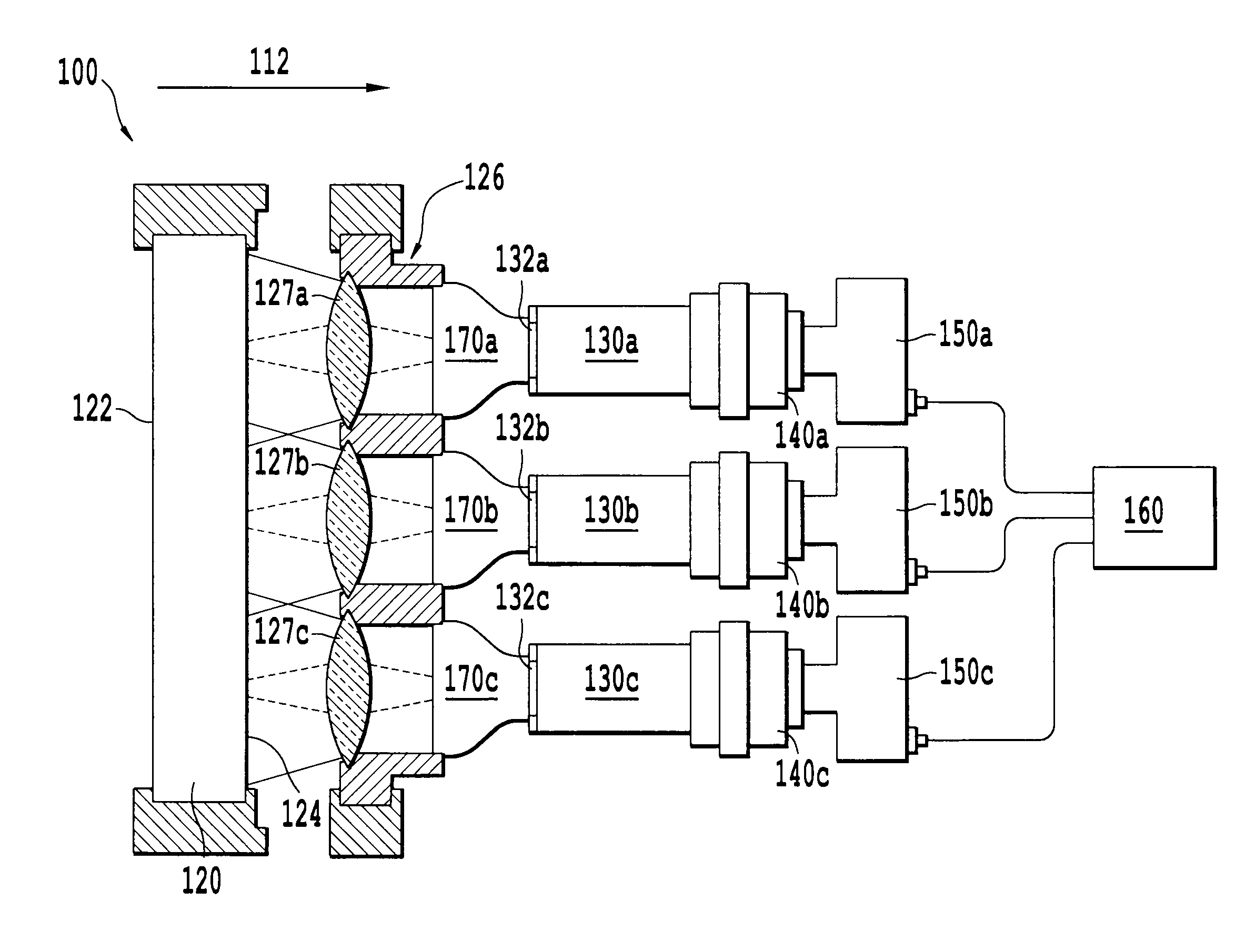
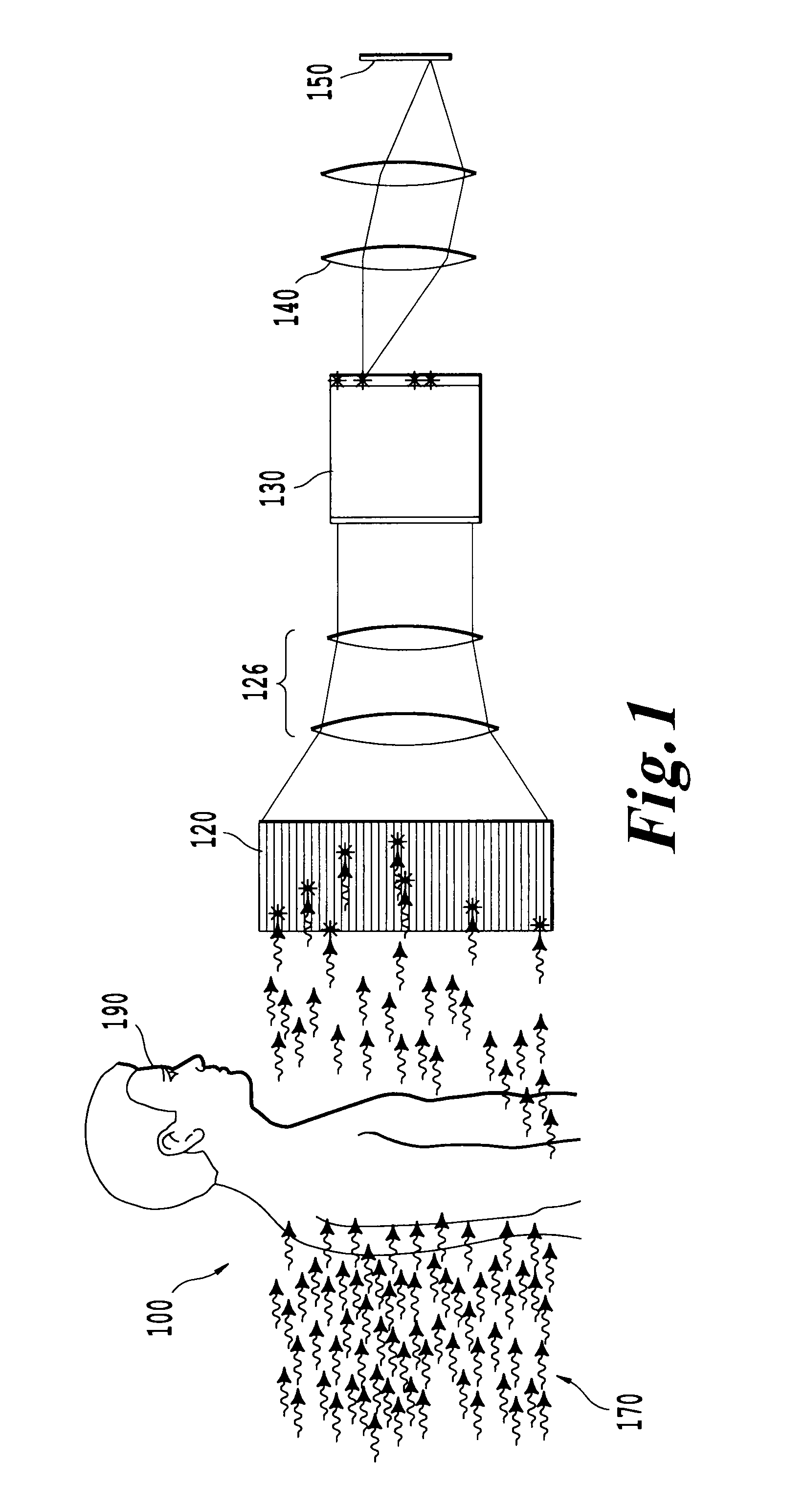
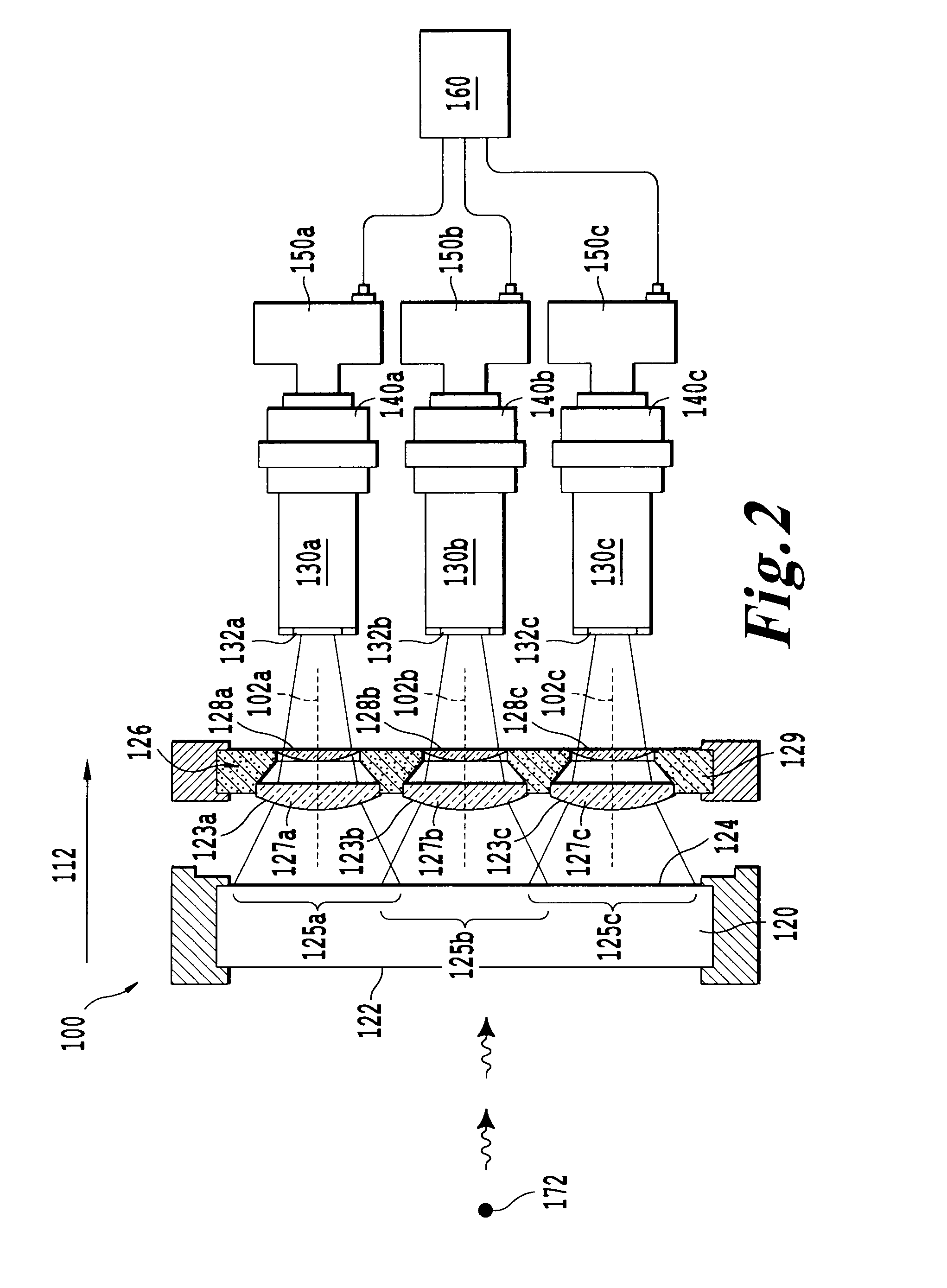
[0019]In accordance with the present invention, a X-ray detector apparatus is schematically illustrated in FIG. 1, referred to throughout by reference numeral 100. In variant, the apparatus 100 can also be configured to capture gamma rays. In apparatus 100, X-rays traverse a subject 190, for example a small animal or a human patient, and the X-rays then impinge on a scintillator plate 120. The scintillator plate 120 converts the X-rays into optical radiation that is emitted from the rear surface of plate 120. A lens system 126 can capture the optical radiation, and can project it onto an image intensifier 130. Intensified optical radiation is emitted from a rear surface of intensifier 130, and is further projected by lens 140 onto solid state detector 150, that can convert the intensified optical radiation into an image. Detector may also include hardware and software for performing data processing. The apparatus 100 is configured for X-ray photon counting, and is thereby able to me...


PUM


Abstract

An X-ray detection device including a scintillator configured to convert gamma rays or X-rays into optical radiation, an optical image intensifier configured to intensify the optical radiation to generate intensified optical radiation, an optical coupling system configured to guide the intensified optical radiation, and a solid state detector configured to detect the intensified optical radiation to generate an interaction image representing an X-ray energy emission and to perform photon counting based on data of the interaction image.

Description

CROSS REFERENCE TO RELATED PATENT DOCUMENTS[0001]The present patent application is a Continuation-In-Part (CIP) of U.S. application Ser. No. 12 / 197,120, filed on Aug. 22, 2008, now being published as U.S. Patent Application Publication 2009 / 0050811, and claiming priority from U.S. Provisional Application Ser. No. 60 / 965,910, filed on Aug. 23, 2007, the present application also claiming priority from U.S. Provisional Application Ser. No. 61 / 195,193, filed on Oct. 3, 2008, all the contents thereof being herewith incorporated by reference.STATEMENT REGARDING FEDERALLY SPONSORED RESEARCH OR DEVELOPMENT[0002]This invention was made with government support under P41 EB002035 awarded by the National Institutes of Health. The government has certain rights in the invention.BACKGROUND OF THE INVENTION[0003](a) Field of the Invention[0004]The present invention relates to a high-resolution, modular X-ray detector based on a scintillator plate, a lens array, and image intensifiers having a stron...

Claims


Application Information

Patent Timeline
Patent Type & Authority Patents(United States)
IPC IPC(8): G01T1/29
CPCG01T1/1642G01T1/2018G01T1/1644A61B6/037
Inventor BARRETT, HARRISON H.FURENLID, LARS R.BARBER, H. BRADFORDMILLER, BRIAN W.
Owner THE ARIZONA BOARD OF REGENTS ON BEHALF OF THE UNIV OF ARIZONA
Learn More