Modifying radiation beam shapes

a collimator and radiation beam technology, applied in the direction of radiation therapy, electrodes and associated parts, therapy, etc., can solve the problem that the leaf itself is not deep enough to attenuate enough, and achieve the effect of reducing radiation intensity, less space, and sufficient clearan

Active Publication Date: 2013-08-27
ELEKTA AB
View PDF7 Cites 8 Cited by
  • Summary
  • Abstract
  • Description
  • Claims
  • Application Information

AI Technical Summary

Benefits of technology

[0008]The present invention is directed to a fully-integrated, LINAC-mounted multi-leaf collimator (MLC) apparatus that includes multiple banks of adjustable leaves that are sized and arranged such that they can be moved into and out of the general radiation field of the LINAC to provide alternate modes of radiation beam shaping. In general, the MLC banks include a “finer” bank of leaves (referred to herein as the “second MLC” or “secondary MLC”) that does not completely block the radiation beam to the same extent as the primary MLC due to their geometry, spacing and arrangement with respect to the primary MLC. For example, although there are no gaps between the leaves of the secondary MLC, the leaves themselves are not deep enough to attenuate enough of the radiation to be considered capable of shielding the patient on their own. As a result, the secondary MLC reduces the radiation intensity in the penumbra of the beam after it has passed through the first MLC, but crucially, can be much shorter / less deep, and therefore take up less space in the LINAC head, maintaining sufficient clearance with respect to the patient, and reducing the amount of extra weight added to the head.

Problems solved by technology

For example, although there are no gaps between the leaves of the secondary MLC, the leaves themselves are not deep enough to attenuate enough of the radiation to be considered capable of shielding the patient on their own.

Method used


Image

  • Modifying radiation beam shapes
  • Modifying radiation beam shapes
  • Modifying radiation beam shapes

Examples


Embodiment Construction

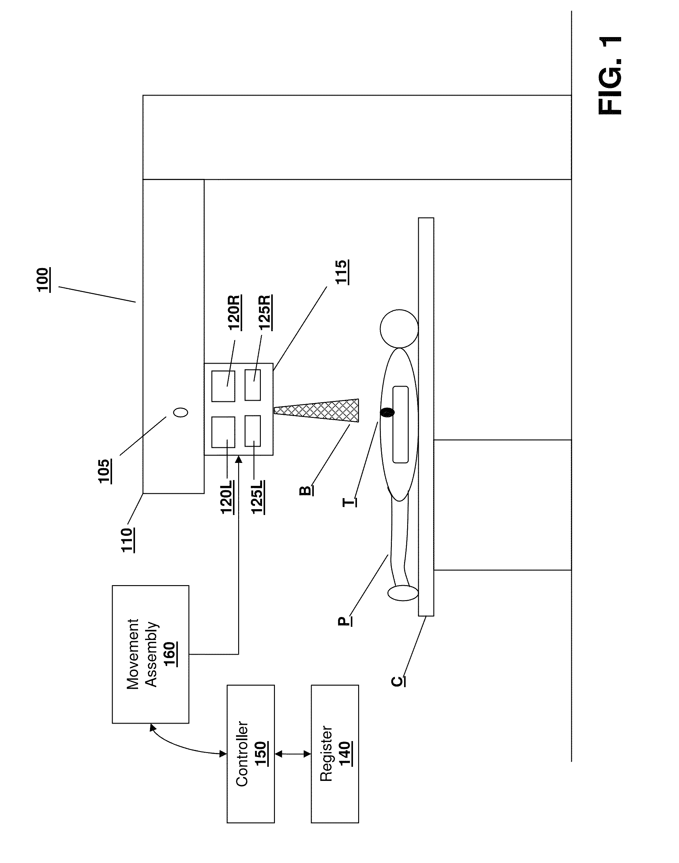
[0025]Referring to FIG. 1, one embodiment of an apparatus and system in accordance with various embodiments of the invention is shown. A linear accelerator (LINAC) 100 is used to generate and deliver a radiation beam B to a patient P supported on couch C. Typically, the beam B is generated by a radiation source 105 contained within the LINAC head 110. A target volume T has previously been identified and defined in or on the patient's body, to which the beam B is to be administered. The volume T may, for example, be a cancerous tumor which is to be treated by introducing the biological effects of the radiation beam from source 105 to the target T according to a radiation treatment and dosage plan.

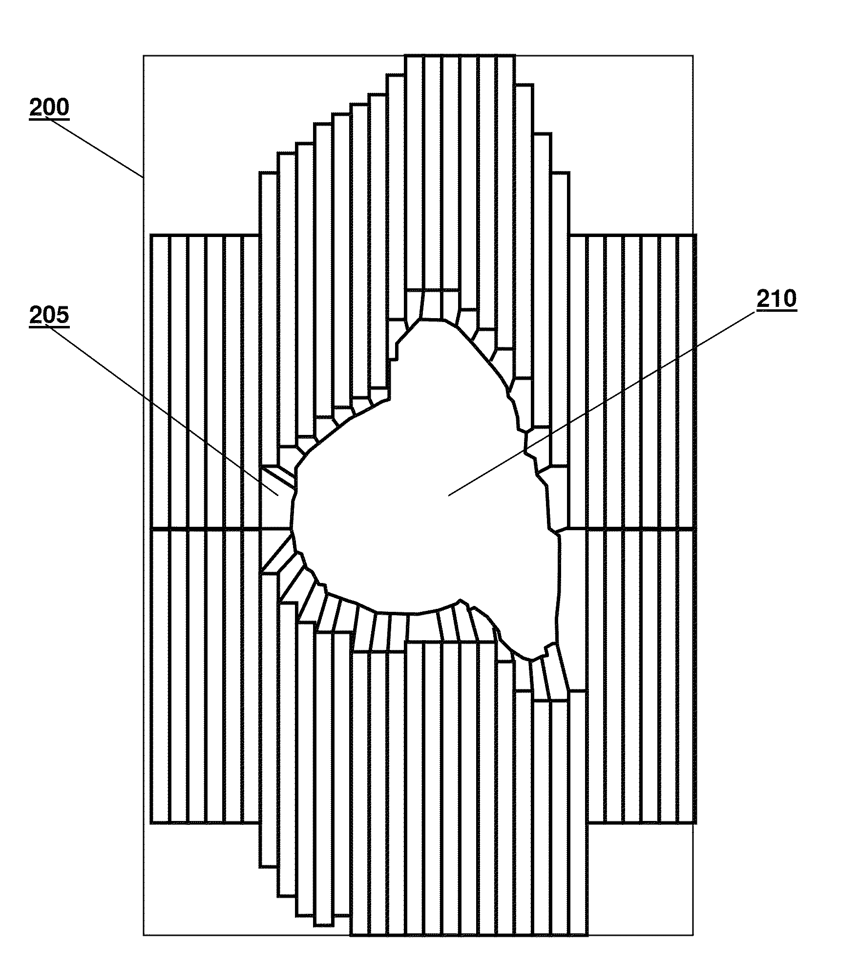
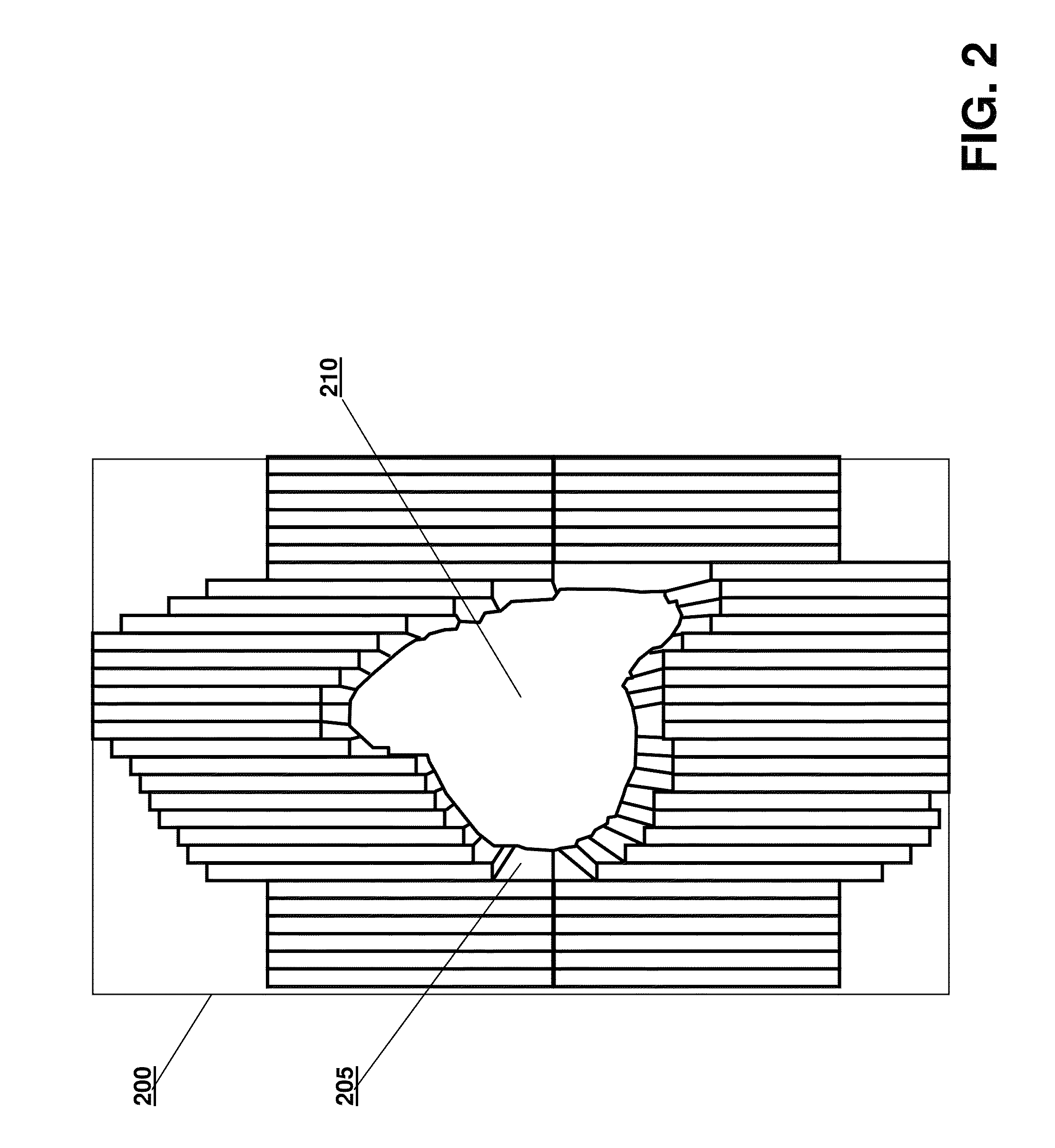
[0026]In order to shape, direct and otherwise control the delivery of the radiation beam B to the patient P, a beam-shielding device such as a multi-leaf collimator (MLC) assembly 115 is attached to or contained within the LINAC head 110 to define a radiation field. Referring to FIG. 1, a be...


PUM


Abstract

A patient's lesion is localized for the purpose of administering radiation treatment by obtaining a beam shape representation along one or more beam directions of a radiation treatment device. An image corresponding to the lesion is obtained from each beam direction, and the beam shape and image are fixed to a common coordinate system to facilitate alignment.

Description

TECHNICAL FIELD[0001]This invention relates to methods and systems for administering radiotherapy treatments and, more particularly, to methods and apparatus for shaping radiation beams using a multi-leaf collimator.BACKGROUND INFORMATION[0002]Radiation-emitting devices are used for the treatment of cancerous tumors within patients. The primary goal of treating cancerous tumors with radiation therapy is the eradication of the cancerous cells, while the secondary goal is to avoid, to the maximum possible extent, damaging healthy tissue and organs in the vicinity of the tumor. Typically, a radiation therapy device includes a gantry that can be rotated around a horizontal axis of rotation during the delivery of a therapeutic treatment. A particle linear accelerator (“LINAC”) is located within the gantry, and generates a high-energy radiation beam of therapy, such as an electron beam or photon (x-ray) beam. The patient is placed on a treatment table located at the isocenter of the gantr...

Claims


Application Information

Patent Timeline
Patent Type & Authority Patents(United States)
IPC IPC(8): G21K5/00
CPCA61N5/1045G21K1/046A61N5/1049
Inventor LUZZARA, MARCO
Owner ELEKTA AB
Why Eureka
Try Eureka