Electromagnetic relay

a technology of electromagnetic relays and contacts, applied in electromagnetic relay details, contact mechanisms, electrical apparatus, etc., can solve the problems of increased manufacturing costs, increased wear at the surface of both fixing contacts and movable contacts, and difficulty in controlling the direction of arcs, so as to inhibit contact wear and increase manufacturing costs.

Inactive Publication Date: 2013-08-27
FUJITSU COMPONENENT LTD
View PDF7 Cites 3 Cited by
  • Summary
  • Abstract
  • Description
  • Claims
  • Application Information

AI Technical Summary

Benefits of technology

[0010]Accordingly, embodiments of the present invention may provide a novel and useful electromagnetic relay solving one or more of the problems discussed above.
[0011]More specifically, the embodiments of the present invention may provide an electromagnetic relay whereby it is possible to inhibit wear of a contact without increasing manufacturing costs and influencing opening and closing capabilities.
[0020]According to the embodiments of the present invention, it is possible to provide an electromagnetic relay whereby it is possible to inhibit wear of a contact without increasing manufacturing costs and influencing opening and closing capabilities.

Problems solved by technology

Thus, heat generated at the anode and the cathode may cause evaporation of the molecules forming the anode and the cathode so that the wear at the surfaces of both the fixing contact and the movable contact may be increased.
Therefore, this structure may cause the wear of the movable spring so that the opening and closing operations of the contact may be influenced.
Therefore, in a case where the contact of an alternating current is opened or closed, since a direction of the arc is periodically changed, it may be, depending on a way of using the magnet, difficult to control the direction of the arc.
As a result, the external dimensions of the electromagnetic relay may be increased so that the manufacturing cost may be increased.

Method used


Image

  • Electromagnetic relay
  • Electromagnetic relay
  • Electromagnetic relay

Examples


first embodiment

[First Embodiment]

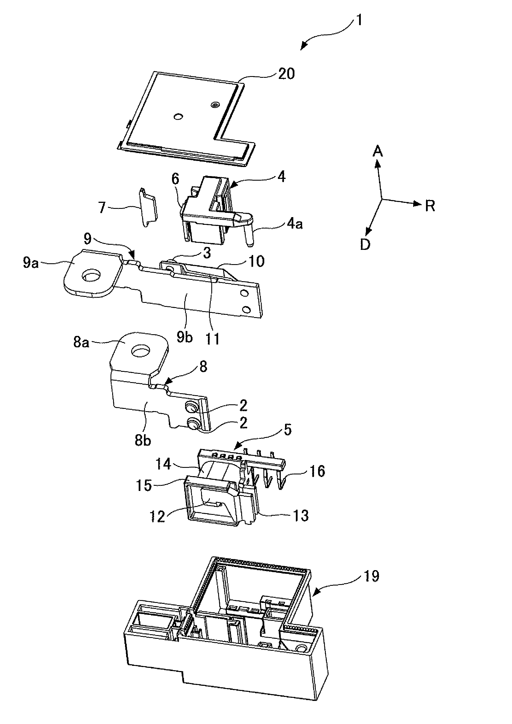
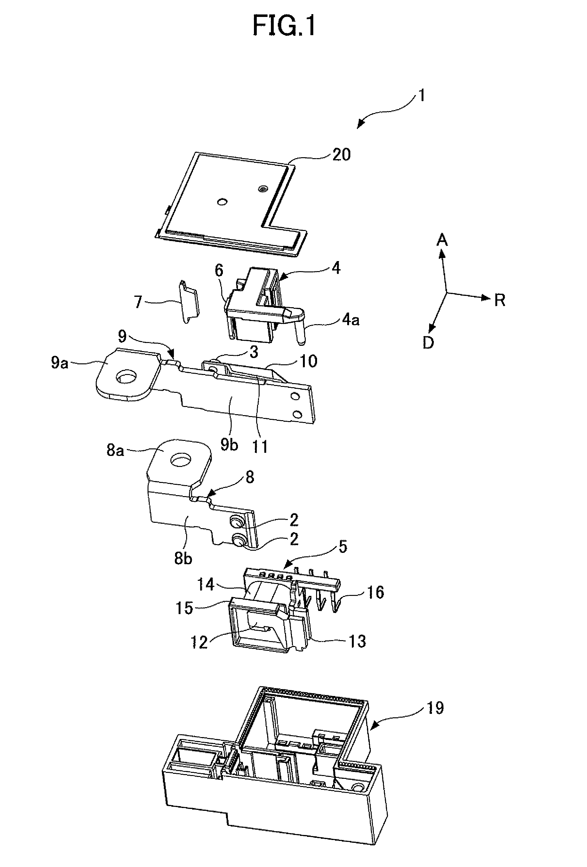
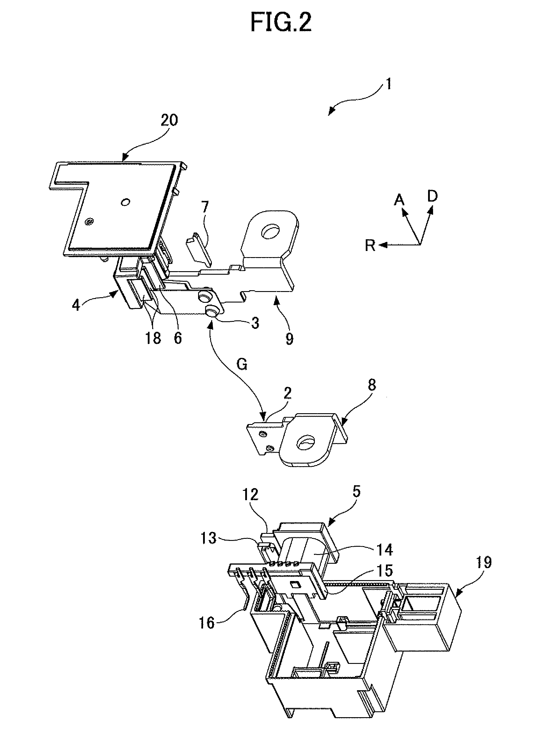
[0033]FIG. 1 through FIG. 3 are first through third schematic, perspective, and exploded views of an electromagnetic relay of a first embodiment of the present invention. More specifically, FIG. 1 through FIG. 3 are schematic and perspective views showing an arrangement in a direction from a base to a cover of each of components of the electromagnetic relay of the first embodiment of the present invention. In drawings which are referred to in the following explanation, “A” denotes a direction from the base to the cover. “R” denotes an extending direction of a flat plate where a terminal part is a starting point of a movable contact side bus bar terminal. “D” denotes a separating direction of the movable contact configured to approach to or be separated from the fixing contact. The direction A, the extending direction R, and the separating direction D are perpendicular to each other. FIGS. 4(a) and 4(b) are schematic views showing a change of a mutual positional rel...

second embodiment

[Second Embodiment]

[0059]FIGS. 7(a) and 7(b) are schematic views showing the arrangement and configuration of a magnetic body 107 and the way of attracting the arc of a second embodiment of the present invention. In FIGS. 7(a) and 7(b), parts that are the same as the parts discussed in the first embodiment, other than a configuration of an air space side magnetic body 107, are given the same reference numerals, and explanation thereof is omitted.

[0060]In an electromagnetic relay of the second embodiment of the present invention, the air space side magnetic body 107 has, as illustrated in FIG. 7(a), a length which covers the entire length of the air space G formed by the fixing contact 2 and the movable contact 3 in the separating direction D. A concave part 107a which narrows toward the external periphery side is provided at a side facing the air space G. The length in the separating direction of the concave part 107a is linearly shorter as being toward the external periphery side. ...

third embodiment

[Third Embodiment]

[0064]FIGS. 8(a) and 8(b) are schematic views showing an arrangement and configuration of a magnetic body and the way of attracting the arc of a third embodiment of the present invention. In FIGS. 8(a) and 8(b), parts that are the same as the parts discussed in the first embodiment, other than a fixing side magnetic body 27, are given the same reference numerals, and explanation thereof is omitted.

[0065]In an electromagnetic relay 1 of the third embodiment, as illustrated in FIG. 8(a), a fixing side magnetic body 27 positioned at an external periphery side of the fixing point 2 is provided. The fixing side magnetic body 27 is fixed to the flat plate part 8b of the fixing side bus bar terminal 8 by, for example, caulking, an adhesive, or the like.

[0066]In the meantime, in any of the first through third embodiments, a signal terminal configured to detect a conductive state between the fixing contact 2 and the movable contact 3 may be provided. This is discussed in a ...


PUM


Abstract

An electromagnetic relay, includes a fixing contact; a movable contact configured to be moved to or from the fixing contact in an approaching and separating direction; a movable part; a driving part configured to drive the movable part; a pressing part configured to press the movable contact based on the driving of the movable part; and a magnetic body provided at an external periphery side of at least one of the fixing contact, the movable contact, and an air space in the approaching and separating direction of the fixing contact and the movable contact.

Description

CROSS-REFERENCE TO RELATED APPLICATIONS[0001]This patent application is based upon and claims the benefit of priority of Japanese Patent Application No. 2009-261172 filed on Nov. 16, 2009, the entire contents of which are incorporated herein by reference.BACKGROUND OF THE INVENTION[0002]1. Field of the Invention[0003]The present invention generally relates to electromagnetic relays. More specifically, the present invention relates to an electromagnetic relay configured to turn on or off electric power of an electrical device for home or industrial use.[0004]2. Description of the Related Art[0005]Under conditions where a voltage applied to a contact configured to perform opening and closing operations in an electromagnetic relay is high and an amount of an electric current flowing into the contact is large, when a fixing contact and a movable contact forming the contact become separated from each other from a state where the fixing contact and the movable contact come in contact with...

Claims


Application Information

Patent Timeline
Patent Type & Authority Patents(United States)
IPC IPC(8): H01H51/22
CPCH01H9/36H01H50/08H01H50/541H01H51/2227H01H51/00
Inventor MORIMURA, MASATO
Owner FUJITSU COMPONENENT LTD
Why Eureka
Try Eureka