Mask assembly, color filter substrate and method of manufacturing the same

a mask and substrate technology, applied in the field of display technologies, can solve problems such as reducing detection accuracy, and achieve the effect of saving manufacturing cost and improving detection accuracy

Inactive Publication Date: 2017-07-06
BOE TECH GRP CO LTD +1
View PDF5 Cites 3 Cited by
  • Summary
  • Abstract
  • Description
  • Claims
  • Application Information

AI Technical Summary

Benefits of technology

[0042]In any of the marking regions of the color filter substrate manufactured by using the mask assembly provided according to the present disclosure, a spacing between centers of two adjacent ones of the photoresist marking blocks located in the same row is equal to a spacing between centers of two adjacent ones of the photoresist blocks located in the same row, such that when manufacturing the color filter substrate, photoresist blocks of different colors and photoresist marking blocks of different colors may be manufactured by using the same one mask, thereby saving manufacturing cost. Further, a spacing between centers of two of the first black matrix marking blocks that are the closet to each other among the first black matrix marking blocks is not less than two times of a spacing between centers of two adjacent ones of the photoresist blocks located in the same row, such that when a detection device is used to detect whether or not the photoresist marking block is aligned with the first black matrix marking block, there will be only one first black matrix marking block within a detection window, and the detection device can determine a central position of the first black matrix marking block only based on a profile of the first black matrix marking block and determine a center of the photoresist marking block corresponding to the first black matrix marking block. Thus, only one set of detection values will be obtained for each detection, thereby improving accuracy of detection result.

Problems solved by technology

Thus, the two photoresist marking blocks cannot be differentiated from each other due to factors such as brightness of light, which will easily result in an error in recognition, thereby reducing accuracy of detection result.

Method used


Image

  • Mask assembly, color filter substrate and method of manufacturing the same
  • Mask assembly, color filter substrate and method of manufacturing the same
  • Mask assembly, color filter substrate and method of manufacturing the same

Examples


Embodiment Construction

[0055]In the following detailed description, numerous specific details are set forth in order to provide a thorough understanding of the disclosed embodiments. It will be apparent, however, that the present disclosure may be practiced with other embodiments different from those described herein. Thus, scopes of the present disclosure are not limited by the following disclosed exemplary embodiments.

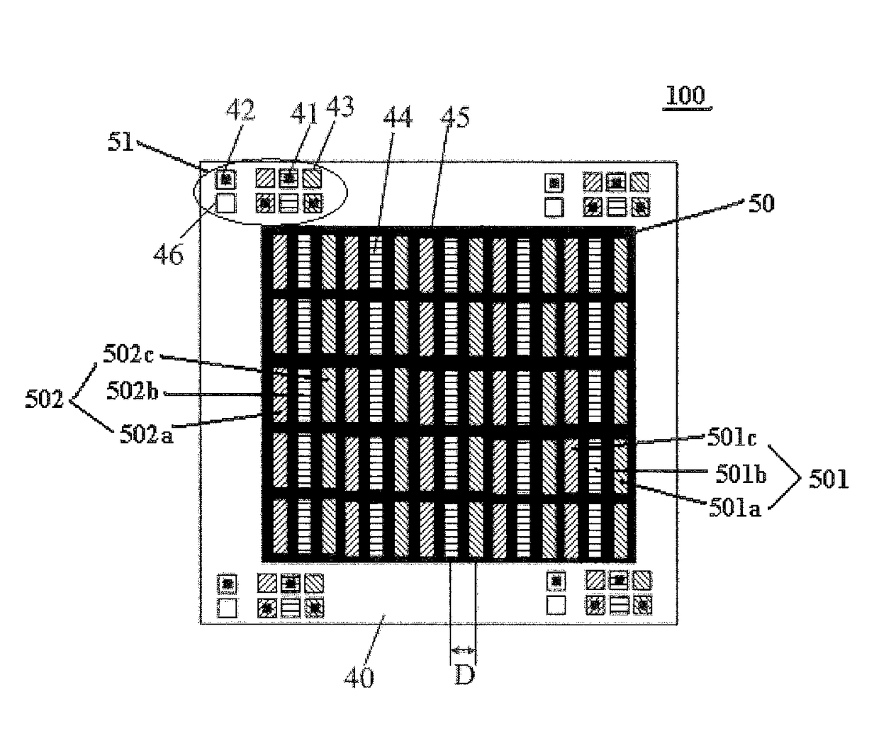
[0056]In a first aspect of the present disclosure, there is provided a mask assembly, for manufacturing a color filter substrate 100. The color filter substrate 100 comprises a color filtering region 50 and a plurality of marking regions 51, and the color filtering region 50 is divided into a plurality of pixel units, for example, pixel units 501 and 502, each comprising a plurality of sub-pixels of different colors arranged in a row direction. For example, the pixel unit 501 comprises sub-pixels 501a, 501b and 501c, and the pixel unit 502 comprises sub-pixels 502a, 502b and 502c. The mask...


PUM

PropertyMeasurementUnit
widthaaaaaaaaaa
widthaaaaaaaaaa
lengthaaaaaaaaaa

Abstract

The present disclosure provides a mask assembly, a color filter substrate and a method of manufacturing the same. The mask assembly includes: a first mask formed with a plurality of first black matrix marking mask patterns at a position corresponding to each marking region, a spacing between centers of two first black matrix marking mask patterns that are the closest to each other among the first black matrix marking mask patterns being not less than two times of a spacing between centers of two adjacent sub-pixels located in a same row; and a second mask formed with a plurality of photoresist block mask patterns at a position corresponding to the color filtering region, and further formed with at least two photoresist marking mask patterns, which are located at a position corresponding to each marking region and arranged in a column direction.

Description

CROSS-REFERENCE TO RELATED APPLICATION[0001]This application claims the benefit of Chinese Patent Applications No. 201610006525.5 filed on Jan. 4, 2016 in the State Intellectual Property Office of China, the disclosures of which are incorporated herein by reference.BACKGROUND OF THE INVENTION[0002]1. Field of the Invention[0003]The present disclosure relates to the field of display technologies, and particularly, to a mask assembly, a color filter substrate and a method of manufacturing the same.[0004]2. Description of the Related Art[0005]A color filter substrate mainly comprises a base substrate, an indium tin oxide film for a back plate, a black matrix, a color filter layer, a layer of protection film and spacers. In order to detect production precision of respective layers, as shown in FIG. 1, the color filter substrate includes a plurality of marking regions located close to corners thereof, and a plurality of black matrix marking blocks 5 and a plurality of photoresist marking...

Claims


Application Information

Patent Timeline
Patent Type & Authority Applications(United States)
IPC IPC(8): G02B5/20G03F7/20
CPCG03F7/70G02B5/201G02F1/1309G02F1/133512G02F1/133514G02F1/133516G03F1/42G09F9/30G02B5/003G02B27/32G03F7/70633
Inventor XIONG, QIANGWU, HONGJIANGBI, RUILINSUN, HONGYUHAN, ZILIPENG, YUANHONGLI, MIN
Owner BOE TECH GRP CO LTD
Why Eureka
Try Eureka