Method for calibrating a measuring system

a technology of measuring system and calibration method, which is applied in the field of calibrating a measuring system, can solve the problems of inability to save time and money, the calibration method of this type is usually too expensive for an industrial production line, and the calibration method is not time-saving and money-saving, etc., and achieves the effect of high accuracy and easy handling

Active Publication Date: 2013-08-27
ISRA VISION SYST AG
View PDF10 Cites 46 Cited by
  • Summary
  • Abstract
  • Description
  • Claims
  • Application Information

AI Technical Summary

Benefits of technology

[0008]The object of the present invention, therefore, is to provide a calibrating method that is easy to ha

Problems solved by technology

Calibration methods based on this approach typically require a great deal of computing power, but they also satisfy the highest requirements on accuracy.
Calibration methods of this type are usually too expensive for an industrial production line, however, and they may not be used in a time-saving and money-saving manner, due, in particular, to post-calibrations that often must be carried out during production.
This makes it difficult to carry out a fully-automated calibration during the on-going process.
This means of attaining the object is not universally usable, however, due to the geometric

Method used


Image

  • Method for calibrating a measuring system
  • Method for calibrating a measuring system
  • Method for calibrating a measuring system

Examples


Embodiment Construction

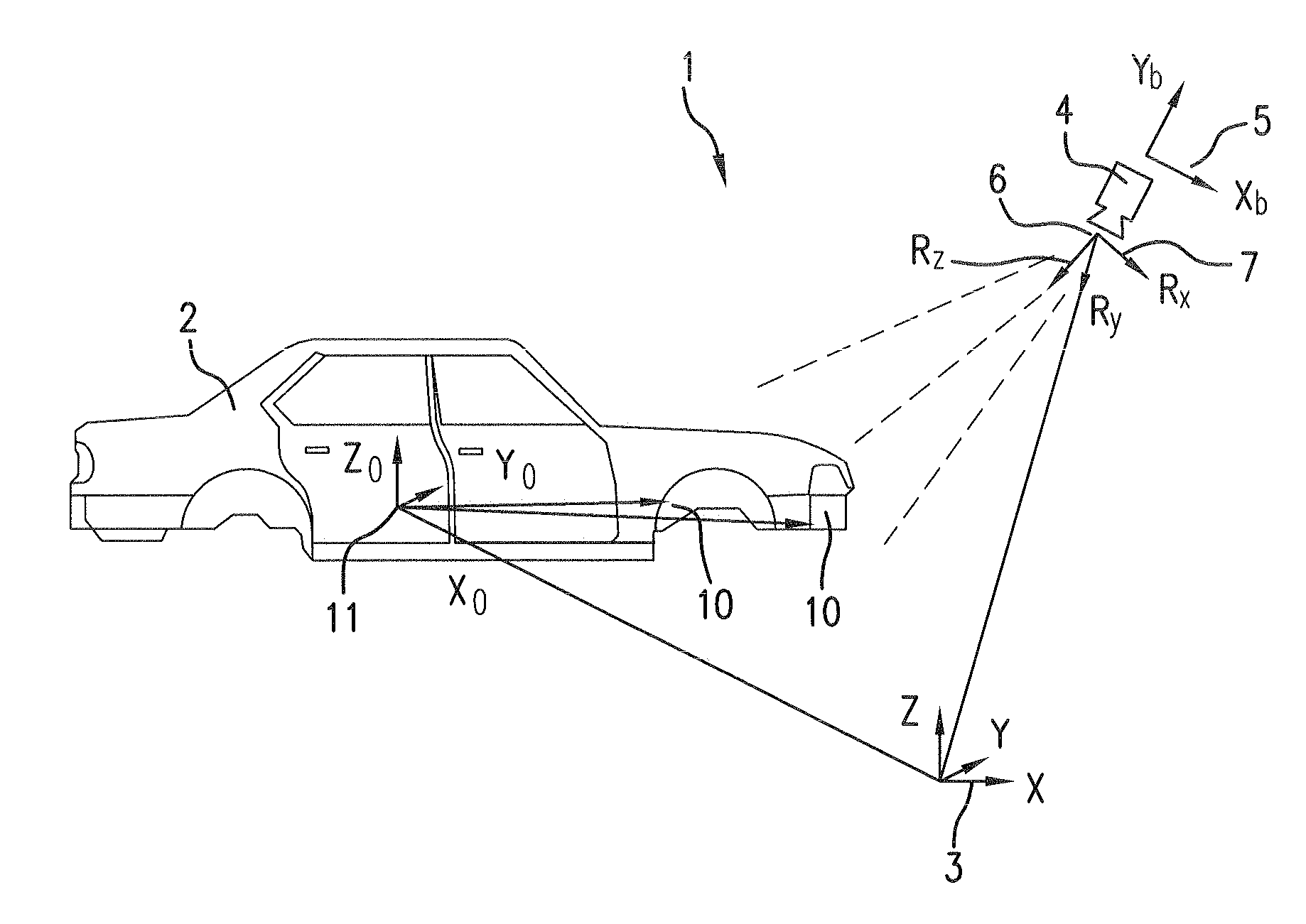
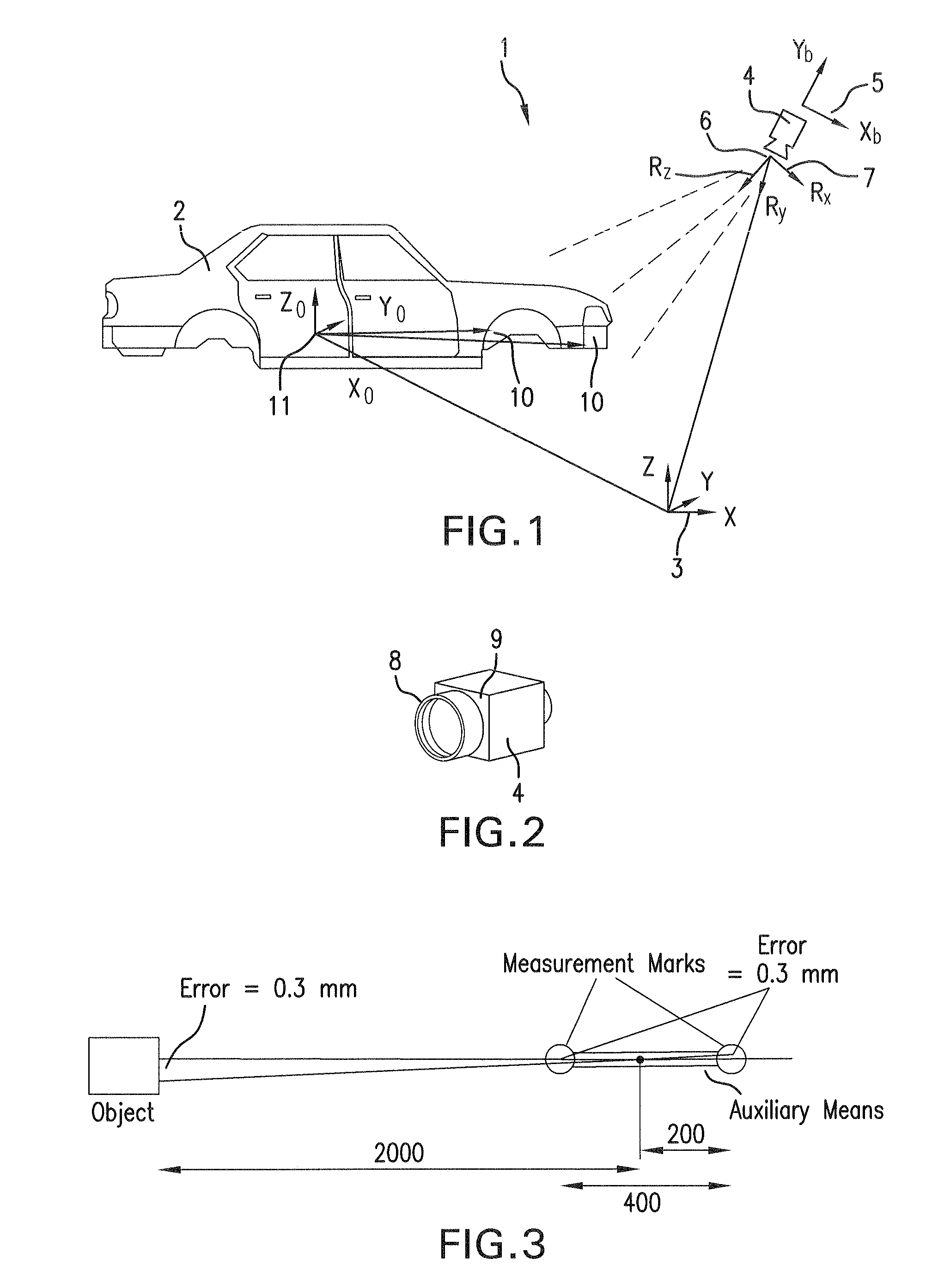
[0026]FIG. 1 is a schematic depiction of a measuring system 1 for determining the position of an object 2 designed as a body in a three-dimensional reference coordinate system 3, which represents the world coordinate system. To this end, object 2 is detected using a calibrated optical camera 4, and the position of object 2 is determined using certain object features.

[0027]Before it is possible to determine the position and orientation of object 2 in coordinate system 3 using measuring system 1, camera 4 must be calibrated when measuring system 1 is started up.

[0028]In this case, “calibration” means establishing an arithmetic relationship between image coordinates Xb, Yb of an image coordinate system 5, camera 4, and a metric reference and / or world coordinate system 3, which generally describes the three-dimensional space with coordinates X, Y and Z. The method used to establish this relationship is to model the physical relationship between the two coordinate systems 3, 5. To this e...


PUM


Abstract

A method for calibrating a measuring system uses at least one camera for determining the position of an object in a reference three-dimensional coordinate system. The external and internal parameters of the camera are calibrated in various steps and the position of the camera is determined with the aid of external measuring means in accordance with three steps. In the first step, the internal camera parameters are ascertained and fixedly assigned to the internal camera. In a second step, the position of the internal camera in the measuring system is determined. In a third step, the orientation of the internal camera is ascertained in the reference three-dimensional coordinate system by evaluating camera images.

Description

BACKGROUND OF THE INVENTION[0001]The present invention relates to a method for calibrating a measuring system based on at least one camera, for determining the position of an object in a reference three-dimensional coordinate system, with which the external and internal camera parameters are calibrated in various steps, and the position of the camera is determined using external measuring means.[0002]Within the framework of the ever-increasing automation of method and production processes using manipulators, e.g., robots, it is necessary to determine the position of objects to be processed in three dimensions, exactly, and in an automated manner, so that the manipulators may grip the objects in a defined manner.[0003]To this end, optical measuring systems are often used that record images of the objects in the working space of the manipulators and evaluate them using image processing, in order to ascertain the orientation of features of the recorded object. Before optical measuring ...

Claims


Application Information

Patent Timeline
IPC IPC(8): H04N7/18G06F19/00G05B15/00
CPCG01B11/002G06T7/0018G06T7/0042G06T2207/30244G06T7/80G06T7/73
Inventor ERSUE, ENIS
Owner ISRA VISION SYST AG
Why Eureka
Try Eureka