Utilization of data center waste heat for heat driven engine

a data center and waste heat technology, applied in the direction of electrical apparatus construction details, operation mode of machines, light and heating apparatus, etc., can solve the problems of increasing amounts of waste heat generated by computers and other electronic components, and achieve the effect of reducing the overall load of alternate heat sources, adequate heat energy, and improving the efficiency of facilities

Inactive Publication Date: 2013-09-03
INDAL IDEA PARTNERS
View PDF45 Cites 36 Cited by
  • Summary
  • Abstract
  • Description
  • Claims
  • Application Information

AI Technical Summary

Benefits of technology

[0011]In the method of the present invention, a heat driven engine, such as an adsorption chiller, may be driven by using the waste heat from the data center as the sole source of the driving heat input. Stated with more specificity, it is the waste heat of the plurality of components, boards, rack / cabinet, equipment, etc. within the data center that may be used to heat a working fluid which is then used to drive the chiller, either directly or indirectly. Alternatively, the waste heat from the equipment in a data center may be combined with other sources of heat to drive a heat driven chiller or heat pump, thereby reducing the overall load on the alternate heat sources and improving the efficiency of the facility's systems. For example, waste heat from a data center may be used to augment the heat from solar panels, fuel cell exhaust, combined cycle plants consisting of one or more diesel engines or gas turbines or steam turbines, or from other boiler processes fired by fuel choices such as coal, oil, natural gas or nuclear power, or it may be combined with the waste heat of other processes.
[0012]It is anticipated that the waste heat generated by typical data centers, alone or augmented, can provide adequate heat energy to the chiller such that the chiller could produce sufficient cold water output to satisfy other cooling needs of the facility, such as auxiliary equipment cooling or industrial process cooling.

Problems solved by technology

As the amount of equipment in a data center increases, and as the number computations or operations per component increase and the speed of individual components increase, the computer and other electronic components will generate increasing amounts of waste heat.

Method used


Image

  • Utilization of data center waste heat for heat driven engine
  • Utilization of data center waste heat for heat driven engine
  • Utilization of data center waste heat for heat driven engine

Examples


Embodiment Construction

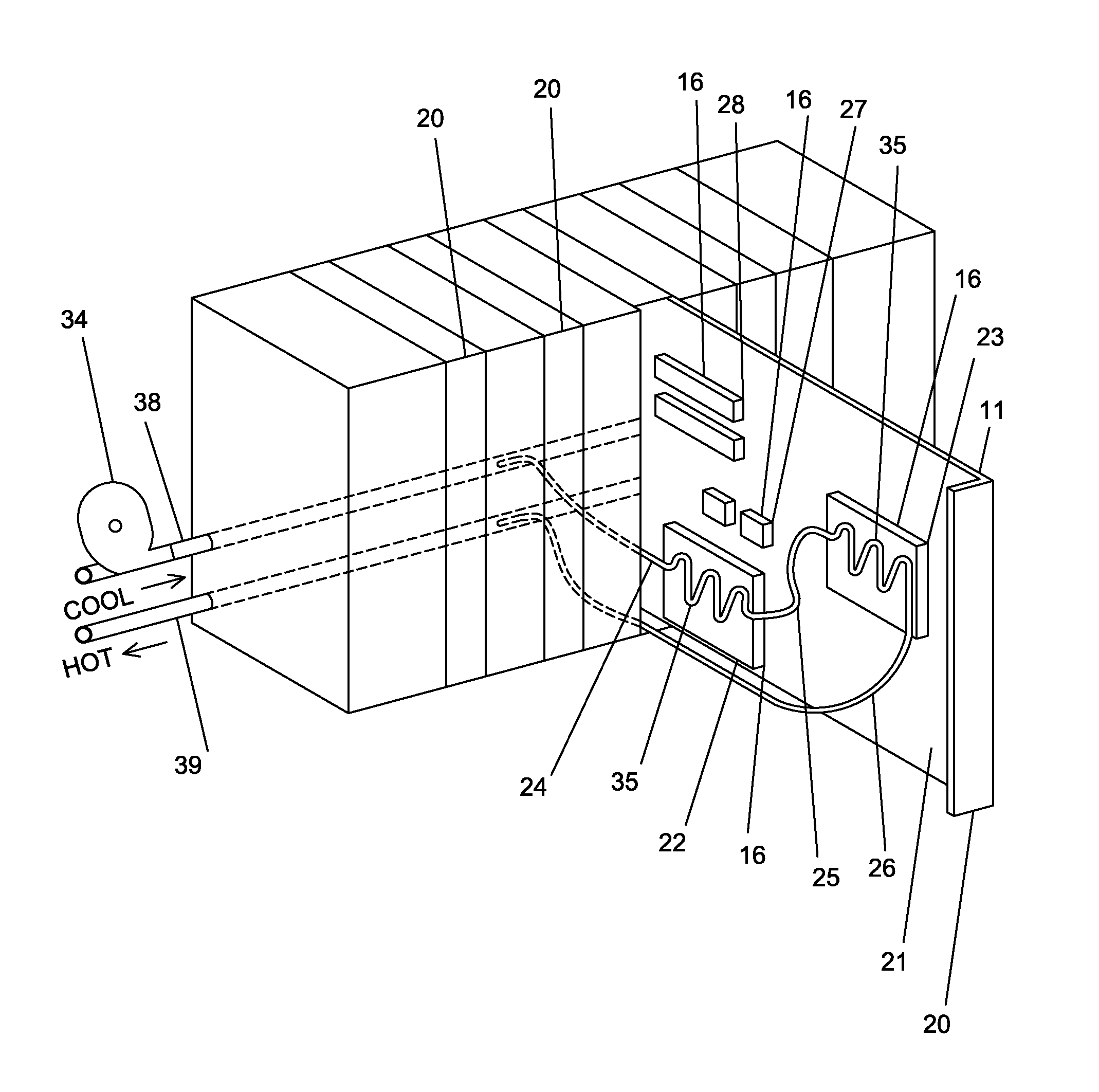
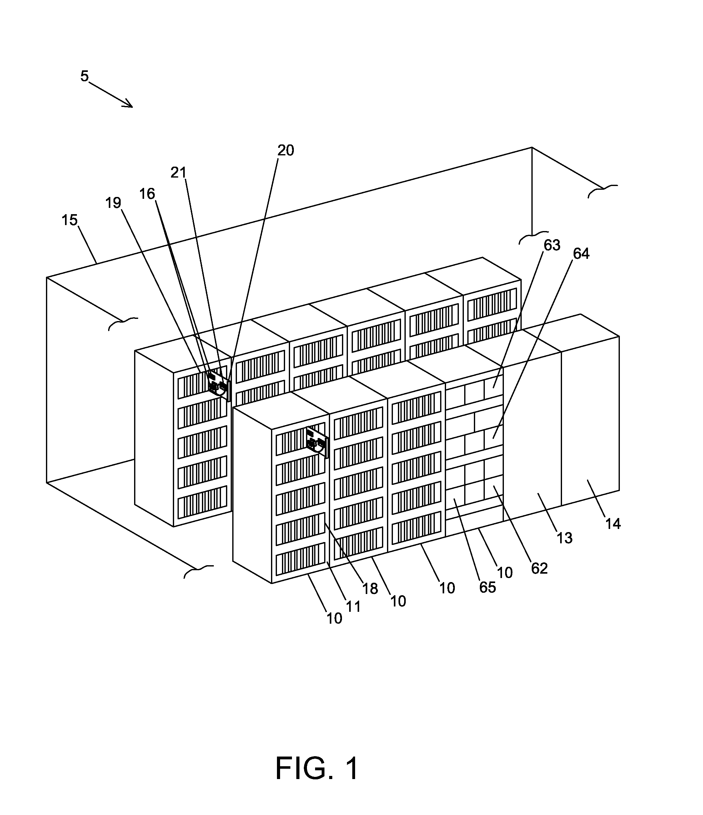
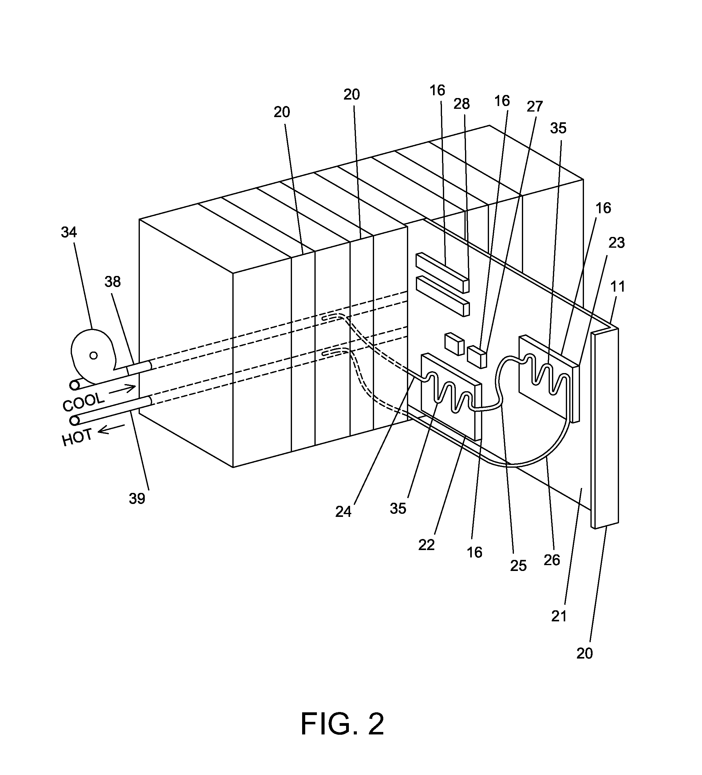
[0019]Data centers and the multiplicity of types of data center equipment located therein are well known in the art. It is also well known that data center equipment generates a significant amount of heat that must be controlled by various means to maintain the data center equipment in working order. While it is not practical to include an exhaustive list of the function and type of every potential type of equipment that might be found in a data center of a business or other organization, for purposes of this disclosure, the term “data center equipment” will be used to refer to any type of heat generating component that one may find useful to locate within a protected environment of an organization's data center or other facility for the collection and installation of computer systems, electronics or controls. Such data center equipment typically comprises, but is not limited to, computer systems, electronics, data storage systems, communications equipment, networking equipment, inf...


PUM


Abstract

A method and system of utilizing waste heat from a plurality of data center equipment comprising the steps of collecting waste heat from a plurality of data center equipment and utilizing said waste heat as the driving heat input for a heat driven engine. Heat recovery means collects waste heat from heat-producing equipment and transfers it in the form of hot water to drive a heat driven engine such as a chiller or heat pump. The output of the heat driven engine may be put to many productive uses, thereby reducing the over all energy load on the data center.

Description

BACKGROUND OF THE INVENTION[0001]This invention relates generally to increasing the efficiently of energy utilization of data centers. Specifically, this invention relates to a method of utilizing the waste heat generated by data centers to increase the overall energy efficiency of the facility of which the data center is a part. This is accomplished by using such waste heat to drive a heat driven engine, such as a heat driven chiller or heat pump.[0002]A heat driven chiller or heat pump may be understood as a “three temperature machine.” Driving heat is input at high temperature, heat is rejected at a medium temperature and heat is adsorbed at a low temperature. In a chiller, the heat adsorbed at the low temperature provides the useful cooling. For purposes of this disclosure, the term “heat pump” will be used to refer to a heat driven engine that provides rejected heat as the useful product.[0003]A data center, sometimes called a server farm, is a facility used to house computer s...

Claims


Application Information

Patent Timeline
Patent Type & Authority Patents(United States)
IPC IPC(8): F25B27/00
CPCF25B27/02H05K7/2079Y02A30/274
Inventor AVERY, RANDAL N.BOOTH, CHARLIELIVINGSTON, WESLOPP, TOM WATSON
Owner INDAL IDEA PARTNERS
Why Eureka
Try Eureka