Brake control system for an electrically driven vehicle

a technology of electrical drive and control system, which is applied in the direction of braking system, analogue process for specific applications, instruments, etc., can solve the problems of fuel or electrical efficiency degradation, unsatisfactory brake feel, etc., and achieve the reduction of fuel consumption, the effect of reducing the amount of fuel consumed and saving electricity

Active Publication Date: 2013-09-03
NISSAN MOTOR CO LTD
View PDF15 Cites 10 Cited by
  • Summary
  • Abstract
  • Description
  • Claims
  • Application Information

AI Technical Summary

Benefits of technology

[0007]In contrast, embodiments of the present invention set a target brake force by eliminating variations in the master cylinder pressure generation points due to mechanical tolerances of the brake components. A comfortable brake feel will thus be achieved while maintaining secure recovery of regenerative energy during regenerative coordinate brake control.
[0009]Therefore, a brake target characteristic is prepared in such a way that, at the actual detected master cylinder pressure generating point, a maximum brake value (between a permissible upper and lower value) to be added to the base brake fluid portion is an appropriate value. Due to the mechanical tolerances of brake system components, such as those caused by manufacturing or assembly tolerances or wear, the actual master cylinder pressure generating points may vary and be delayed or advanced as compared to that originally designed on a theoretical basis. However, in whichever direction they vary, a maximum add-on brake characteristic value is set to be the maximum value with a tolerable range at the actual MC pressure generating points, and based on this setting a variable target brake characteristic is determined. Therefore, even if the actual master cylinder pressure generating point should be delayed from the designed generating point, no suppression of increase of brake target force is experienced up to the MC pressure generating point with the advance of brake pedal stroke. Thus a comfortable brake feel is achieved. Conversely, even if the actual master cylinder pressure generating point advances with respect to the originally designed generating point, a suppression of increase in brake target force is avoided. In addition, recovery of regenerative energy for fuel and electricity savings is secured.
[0010]As a result, when the vehicle is under regenerative braking conditions, an appropriate brake target force may be set by compensating for the variations in MC pressure generating points due to mechanical tolerances or wear, and both a comfortable brake feel and a secure recovery of regenerative braking energy are assured.

Problems solved by technology

Due to this arrangement, the actual point of the brake pedal stroke may differ from that designed value due to mechanical tolerances of brake related components, which can ultimately lead to an unpleasant brake feel.
Conversely, if the actual master cylinder pressure generation point is earlier than designed, the driver demand deceleration will be kept low as the target deceleration and a regenerative recovery of energy is restricted, causing a deterioration in fuel or electrical efficiency.

Method used


Image

  • Brake control system for an electrically driven vehicle
  • Brake control system for an electrically driven vehicle
  • Brake control system for an electrically driven vehicle

Examples


Embodiment Construction

[0027]The following is an explanation of certain embodiments of a brake control system for an electrically driven vehicle with reference to the drawings.

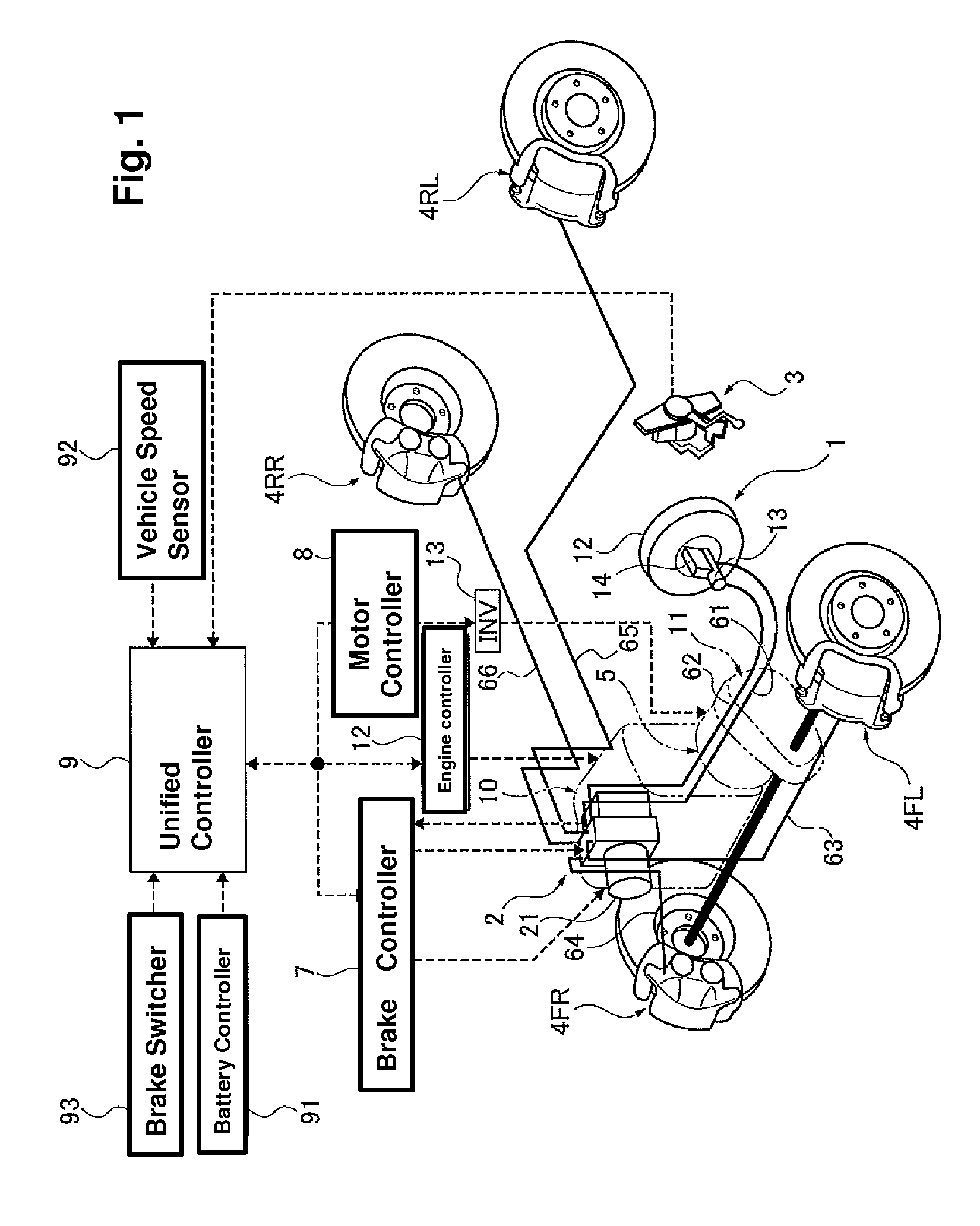
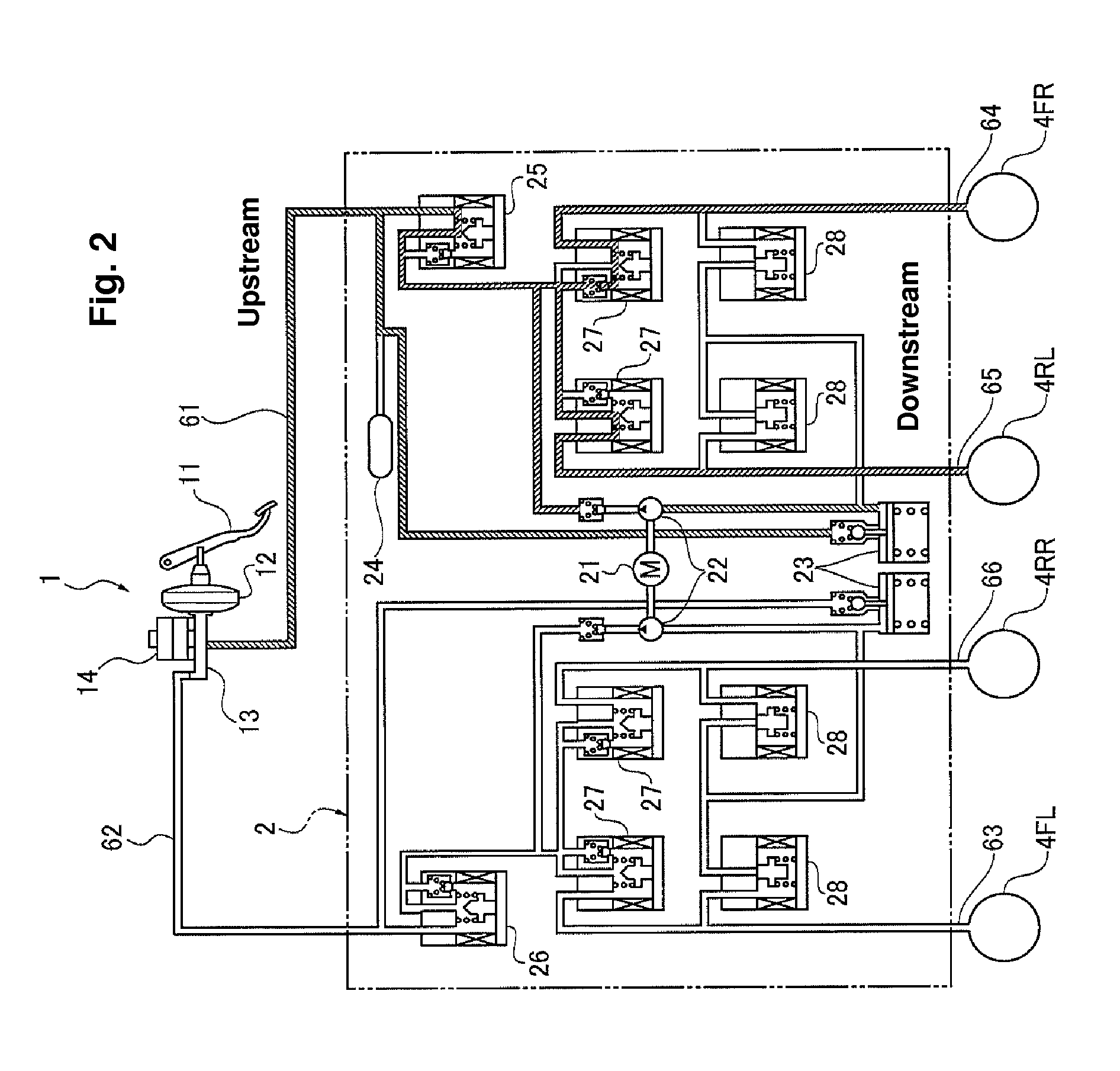
[0028]FIG. 1 shows a system configuration of a hybrid electric vehicle (HEV) of a front wheel drive type to which a brake control system according to embodiments of the present invention can be applied. FIG. 2 illustrates a VDC brake system as an example of brake fluid pressure actuator. Below is an explanation of regenerative coordinate brake system with references to these drawings.

[0029]A brake deceleration generating mechanism of the brake control system according to this example includes a brake fluid pressure generating unit 1, a VDC brake fluid unit 2 (also called a brake fluid pressure actuator), a stroke sensor 3 for detecting a brake pedal stroke, wheel cylinders, specifically a left front wheel cylinder (4FL), a right front wheel cylinder (4FR), a left rear wheel cylinder (RL), and a right rear wheel cylinder (4RR), and a...


PUM


Abstract

During regenerative coordinate braking control, a target brake force is defined by eliminating influences of brake system component tolerances to achieve a comfortable brake feel and secure regenerative energy. A brake control system includes a master cylinder, wheel cylinders, a VDC brake fluid pressure unit and a motor controller. In response to a brake pedal operation by a driver, a brake pedal stroke position is detected at which a pressure in a master cylinder actually begins to be generated. A target deceleration characteristic is adjusted from a theoretical characteristic so that the target deceleration equals a maximum value of an add-on brake force (i.e., the regenerative brake gap) at the detected brake pedal stroke position.

Description

CROSS REFERENCE TO RELATED APPLICATION[0001]This application claims priority to Japanese Patent Application No. 2010-270185, filed Dec. 3, 2010, which is incorporated herein in its entirety by reference.TECHNICAL FIELD[0002]The present invention generally relates to a brake control system applicable to electrically driven vehicles, such as hybrid, electric and fuel cell vehicles, that performs a generative coordinate brake control and achieves a target brake performance.BACKGROUND[0003]In Japanese Unexamined Patent Application No. 2006-096218, a conventional brake device for a vehicle is disclosed. A driver input amount is detected by a brake pedal stroke or master cylinder pressure, for example, and based on the detected driver input and a driver demand deceleration characteristic map, driver demand deceleration is calculated. To achieve this calculated demand deceleration, an add-on brake force will be generated to the vacuum booster output from a master cylinder (basic brake flui...

Claims


Application Information

Patent Timeline
Patent Type & Authority Patents(United States)
IPC IPC(8): B60T8/64B60T8/17
CPCB60T1/10B60T7/042B60T8/4872B60T13/586B60L7/18B60L7/26B60T13/662B60L2240/12B60T2270/604
Inventor MORISHITA, SHINICHIRO
Owner NISSAN MOTOR CO LTD
Why Eureka
Try Eureka