Bearing structure and manufacturing method thereof

a technology of bearing structure and manufacturing method, which is applied in the direction of connecting rod bearings, bearing unit rigid support, mechanical apparatus, etc., can solve the problems of complex processing, high manufacturing cost, and no conventional technique including patent literatures 1 and 2 directs the attention to step development, so as to prevent positional offset, reduce manufacturing cost, and reduce manufacturing cost

Inactive Publication Date: 2013-09-03
JTEKT CORP
View PDF22 Cites 4 Cited by
  • Summary
  • Abstract
  • Description
  • Claims
  • Application Information

AI Technical Summary

Benefits of technology

[0028]The present invention has been made in view of these circumstances, and its object is to provide a bearing structure and a manufacturing method thereof, in which the processing during the manufacture is easy, and the manufacturing cost can be reduced. Further, it is an object to provide a bearing structure, in which the development of a step due to elastic deformation by a rolling element load can be prevented, and a bearing structure in which a positional offset of two-division outer rings in both a circumferential direction and an axial direction of a housing can be suppressed, and the two two-division rings are integrated with each other and can be prevented from being separated.Means for Solving the Problem
[0066]Further, in the bearing structure and the manufacturing method of the present invention, there are achieved excellent advantages that the development of a step due to the elastic deformation by the rolling element load can be prevented and that a positional offset of the two-division outer rings in both the circumferential direction and the axial direction is suppressed, and also the two two-division outer rings are integrated with each other and can be prevented from being separated.

Problems solved by technology

However, the heretofore-proposed divided-type rolling bearing devices and manufacturing methods thereof have the following problems.
In the bearings described in Patent Literatures 1 and 2, there are problems that the inclined portions, the V-shaped convex portions and so on need to be formed at the circumferential end portions of the two-division outer rings and that the processing is complicated, and because of this, the manufacturing cost becomes high.
However, none of the conventional techniques including Patent Literatures 1 and 2 do not direct the attention to the step developing during the rolling movement of the rollers.
In the divided-type rolling bearing device described in the above Patent Literature 3, the rotation prevention portions of the outer rings are formed by the press-shaping processing, and also the corresponding holes are formed in the housing, and therefore the number of the process steps increases, and therefore the manufacturing cost becomes high.

Method used


Image

  • Bearing structure and manufacturing method thereof
  • Bearing structure and manufacturing method thereof
  • Bearing structure and manufacturing method thereof

Examples


first embodiment

[0084](First Embodiment)

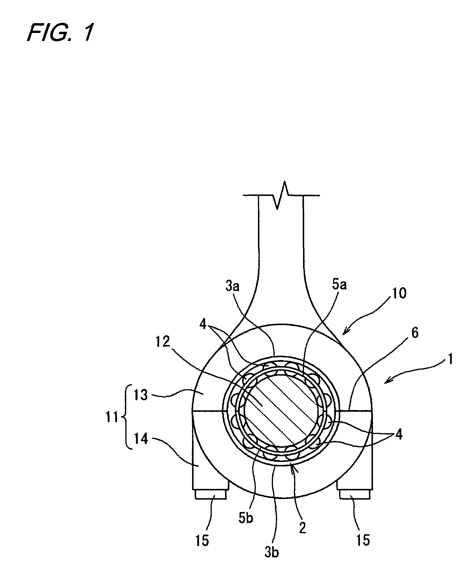
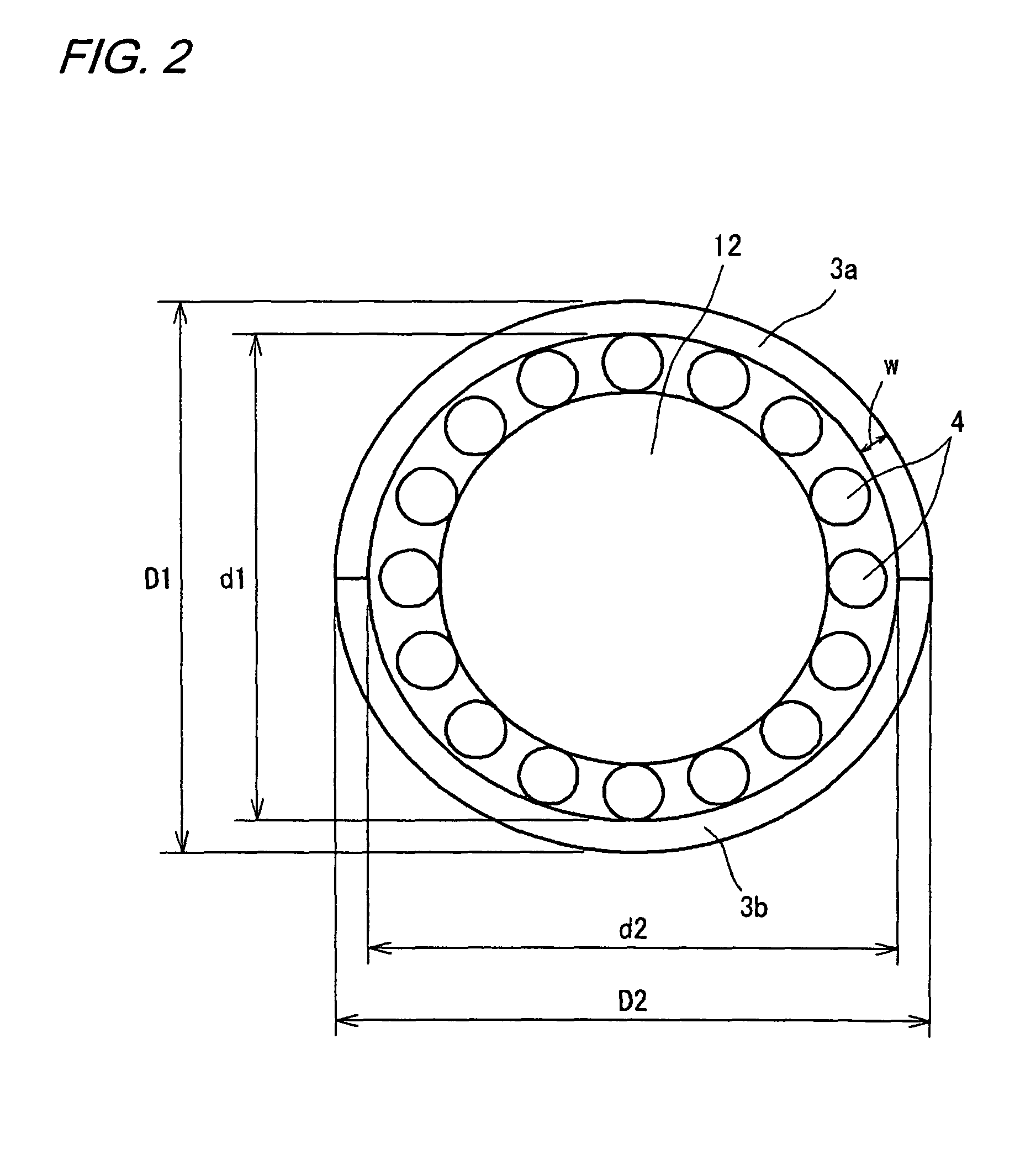
[0085]FIG. 1 is a cross-sectional explanatory view of a larger end portion of a con rod (connecting rod) to which a bearing structure 1 according to a first embodiment of the present invention is applied. The con rod 10 is supported at its larger end portion 11 on a crankshaft 12, and a piston (not shown) is mounted on its smaller end portion side (not shown) through a pin.

[0086]The larger end portion 11 is constructed such that a cap portion 14 serving as a second housing portion and having a cross-sectionally generally-semicircular concave portion is fastened and fixed by bolts 15 to a body portion 13 serving as a first housing portion and having a cross-sectionally generally-semicircular concave portion, thereby forming a cross-sectionally generally-circular support hole 16. A two-division rolling bearing 2 is incorporated in the cross-sectionally generally-circular support hole 16 formed by the body portion 13 and the cap portion 14.

[0087]The rolling bear...

second embodiment

[0095](Second Embodiment)

[0096]FIG. 5 is a cross-sectional explanatory view of a larger end portion 111 of a connecting rod 110 adopting a bearing structure 101 which is a second embodiment of the present invention. The connecting rod 110 has such a structure that a two-division rolling bearing 102 is incorporated in a support hole 116 of the larger end portion 111 which is a housing formed by a first housing section 113 and a second housing section 114, and a crankshaft 112 is further internally fitted thereto. In the present specification, the bearing structure 101 means the structure comprising the housing (the first housing section 113, the second housing section 114 in FIG. 5), and the two-division bearing 102.

[0097]The two-division bearing 102 comprises two-division outer rings 103a, 103b, a plurality of rolling elements 104, 104 so mounted as to be able to roll on inner side surfaces of the two-division outer rings 103a, 103b, and two-division cages 105a, 105b holding the plu...

third embodiment

[0110][Third Embodiment]

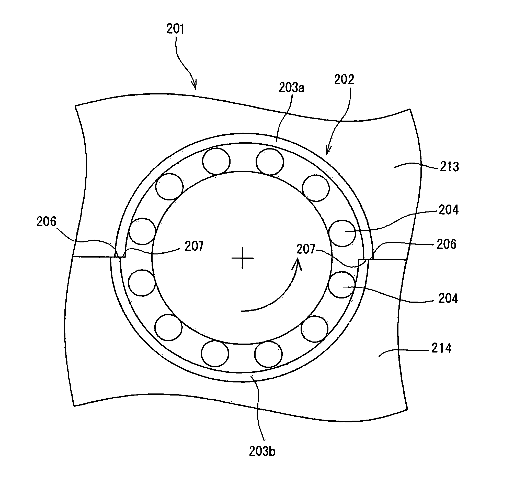
[0111]FIG. 9 is a cross-sectional explanatory view of a larger end portion of a con rod to which a bearing structure 201 according to a third embodiment of the present invention is applied. The con rod 210 is supported at its larger end portion 211 on a crankshaft 212, and a piston (not shown) is mounted on its smaller end portion side (not shown) through a pin.

[0112]The larger end portion 211 is constructed such that a cap portion 214 serving as a second housing and having a cross-sectionally generally-semicircular concave portion is fastened and fixed by bolts 215 to a body portion 213 serving as a first housing and having a cross-sectionally generally-semicircular concave portion, thereby forming a cross-sectionally generally-circular support hole 216. A two-division rolling bearing 202 is incorporated in the cross-sectionally generally-circular support hole 16 formed by the body portion 213 and the cap portion 214.

[0113]The rolling bearing 202 comprises a...


PUM

PropertyMeasurementUnit
bore diameteraaaaaaaaaa
elastic deformationaaaaaaaaaa
bearing structureaaaaaaaaaa

Abstract

A bearing structure includes a housing including a first housing portion and a second housing portion forming together with the first housing portion, a cross-sectionally generally-circular support hole, and a rolling bearing including a pair of outer rings mounted within the support hole of the housing in closely-contacted relation thereto, a plurality of rolling elements mounted to be able to roll on inner side surfaces of the pair of outer rings, and a pair of cages holding the rolling elements. The first housing portion and the second housing portion are mounted in an offset relation to each other in a radial direction so that at mating surfaces of circumferential end portions of the pair of outer rings, the outer ring end portions disposed at an upstream side with respect to a direction of rotation of the shaft form radially inwardly-projecting steps, respectively.

Description

BACKGROUND OF THE INVENTION[0001]The present invention relates to a bearing structure and a manufacturing method thereof. More specifically, the invention relates to a bearing structure comprising a divided-type rolling bearing suitable for supporting a shaft such as a crankshaft and a camshaft in an engine and a housing for supporting the rolling bearing, and also relates to a manufacturing method thereof.[0002]In an engine of an automobile, a ship or others, a bearing for supporting a crankshaft for converting a reciprocal movement of a piston into a rotational movement is disposed between counterweights or between a counterweight and a con rod larger end portion, and therefore a divided-type bearing (two-division bearing) divided circumferentially into two sections has been used as it.[0003]A slide bearing has heretofore been used as the above supporting bearing. However, in recent years, there is an increasing demand for engines having a less fuel consumption, and therefore it h...

Claims


Application Information

Patent Timeline
Patent Type & Authority Patents(United States)
IPC IPC(8): F16C33/58F16C19/00
CPCF16C9/04F16C35/067F16C33/51F16C33/60Y10T29/4968F16C2360/22
Inventor YAMAKAWA, KAZUYOSHISADA, TAKASHI
Owner JTEKT CORP
Why Eureka
Try Eureka