
View-point guided weapon system and target designation method

a guided weapon and target technology, applied in navigation instruments, using reradiation, instruments, etc., can solve the problems of imposing limitations on operations, affecting the accuracy of target designation, so as to reduce the dwell time of active designation

Active Publication Date: 2013-09-03
ROSEMOUNT AEROSPACE
View PDF52 Cites 15 Cited by
  • Summary
  • Abstract
  • Description
  • Claims
  • Application Information

AI Technical Summary

Benefits of technology

The technology described in the patent allows for a forward observer to use a laser target designator to designate a target for a missile or other weapon. The system records a video sequence of the expected view from the weapon in flight to the target impact. The guidance module on the weapon is passive in flight, minimizing the time it takes to designate a target. The technology also allows multiple forward observers to designate multiple targets, and can switch between laser and imager guidance modes. It includes methods for locking onto a target after launch, as well as smoother weapon maneuvering and target re-designation. The technology optimizes weapon costs and performs as well as higher-performance systems.

Problems solved by technology

By being in the target vicinity, the LDO such as a forward observer or designator aircraft and the associated crew, are in danger.
Active laser guided weapons which are designate-until-impact impose limitations on operations.
However, passive image guided weapons require a means to detect and acquire a target autonomously.
These methods are limited in operation due to the large number of possible closure geometries and environmental conditions required in the preloaded target images.
Such systems require an on-board high-resolution, variable magnification lens system, which greatly increases the cost and complexity of the weapon.
Further, such systems do not have a direct assessment at launch time of the weapon's ability to acquire or maintain lock using the preloaded images.
Lacking this assessment to compute a probability of success metric leads to weapon launches that fail to acquire a lock and thus never strike the intended target.
Such a failure requires a post mission analysis to determine why the weapon failed and reduces the confidence in the system.
However, these kinds of combined systems are also very costly and complex, particularly considering that the entire weapon is intended to be expendable.
However, these systems require that the images in the database be accurately geo-referenced, which is a costly process.

Method used


Image

  • View-point guided weapon system and target designation method
  • View-point guided weapon system and target designation method
  • View-point guided weapon system and target designation method

Examples


Embodiment Construction

[0031]The present invention overcomes many of the problems associated with the prior art of weapon guidance systems. The advantages, and other features of the weapon guidance systems disclosed herein, will become more readily apparent to those having ordinary skill in the art from the following detailed description of certain preferred embodiments taken in conjunction with the drawings which set forth representative embodiments of the present invention and wherein like reference numerals identify similar structural elements.

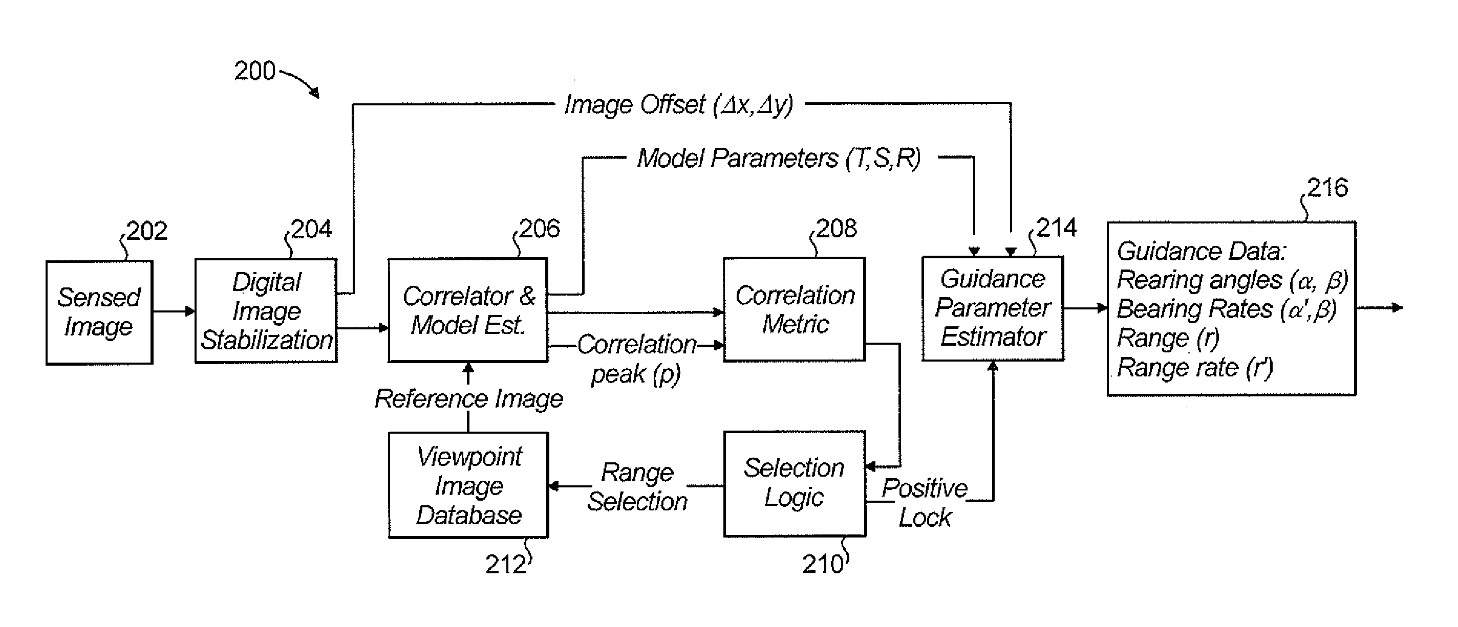
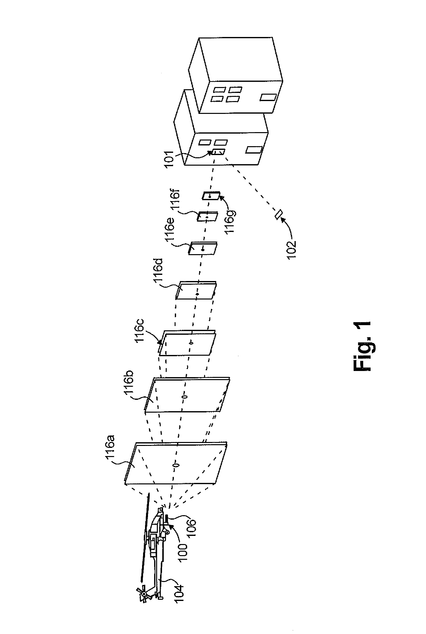
[0032]Referring now to FIG. 1, a viewpoint image creation sequence of a designated target using a viewpoint capture system (VCS) 100 and laser target designator (LTD) 102 in accordance with the subject technology is shown. The LTD 102 is optional as discussed hereinbelow. The VCS 100 is on-board a rotary wing aircraft 104 (shown) or fixed wing aircraft as the case may be. The aircraft 104 also carries a payload of one or more weapons 106 such as a missile with a ...


PUM


Abstract

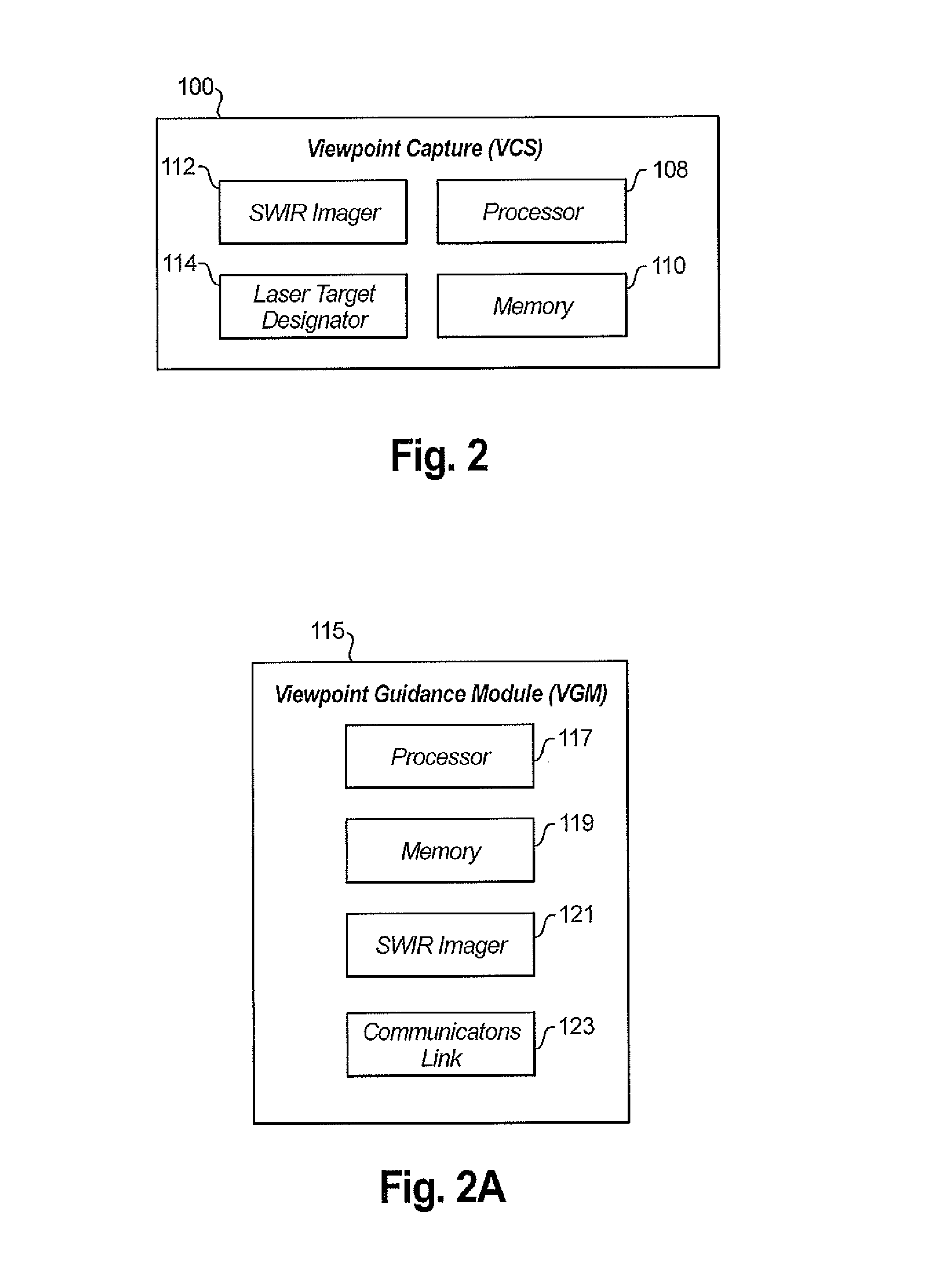
A passive guidance system including a viewpoint capture system (VCS) including a first processor in communication with first memory and a first SWIR imager for creating a viewpoint image database having a plurality of images, at least one of the images having a target point. A weapon guidance module is in communication with the VCS and coupled to a weapon. The weapon guidance module includes a second processor in communication with second memory and a second SWIR imager for storing the viewpoint image database and correlating in-flight images from the second SWIR imager to provide guidance commands directing the weapon to the target point.

Description

BACKGROUND OF THE INVENTION[0001]1. Field of the Invention[0002]The subject disclosure relates to guided weapon systems, and more particularly to an improved guidance system employing an imager and a method for designating a target which provides precision strike capability but that does not need the active-designate-until-impact requirement.[0003]2. Background of the Related Art[0004]Typical weapon guidance systems utilize target designation systems to achieve high accuracy hit-placement. In existing technology, a semi active laser (SAL) target designator (LTD) is used to illuminate an intended target or a chosen spot on a target. The weapon system homes in on illumination reflected from the target to strike the target. These laser guided weapons require the laser designator operator (LDO) to designate the target until weapon impact. Hence, the laser designator operator must remain in the target vicinity. By being in the target vicinity, the LDO such as a forward observer or design...

Claims


Application Information

Patent Timeline
IPC IPC(8): F41G7/34F41G7/00
CPCF41G3/145F41G7/007F41G7/2293F41G7/2253F41G7/2226
Inventor ELL, TODD A.RUTKIEWICZ, ROBERT D.
Owner ROSEMOUNT AEROSPACE
Learn More