Horizontal-axis hydrokinetic water turbine system

a horizontal-axis, hydrokinetic technology, applied in the direction of electric generator control, vessel construction, marine propulsion, etc., can solve the problems of high energy extraction efficiency, difficult transportation and installation, and low cost effectiveness of commercially available water turbine systems, so as to reduce weight and waterway disturbance, increase buoyancy and efficiency, and reduce weight

Active Publication Date: 2013-09-03
DLZ
View PDF35 Cites 13 Cited by
  • Summary
  • Abstract
  • Description
  • Claims
  • Application Information

AI Technical Summary

Benefits of technology

[0009]Disclosed are hydrokinetic water turbine systems that are an improvement over the existing hydrokinetic turbine systems described above. Disclosed is a hydrokinetic water turbine system configured to be placed in a flowing stream of water. The hydrokinetic water turbine system comprises, in combination, a frame structure, a shaft rotatably supported by the frame structure to rotate about a horizontally-disposed central axis of the shaft, and a rotor secured to the shaft and having a plurality of spaced-apart blades so that the flowing stream of water revolves the rotor about the central axis of the shaft. The blades are hollow and filled with a foam material to reduce weight and waterway disturbance and increase buoyancy and efficiency. When the blades are additionally extruded of aluminum and internally braced, this technique allows for reduced weight and increased buoyancy while maximizing structural strength.
[0010]Also disclosed is hydrokinetic water turbine system configured to be placed in a flowing stream of water that comprises, in combination, a substantially rectangular and open frame structure, a shaft rotatably supported by the frame structure to rotate about a horizontally-disposed central axis of the shaft, and a rotor secured to the shaft and having a plurality of spaced-apart blades so that the flowing stream of water revolves the rotor about the central axis of the shaft. The frame structure comprises frame members adapted to reduce a coefficient of drag of the frame structure. When the frame members have a profile that is the same as the blades and thus have a configuration that minimizes drag forces due to the frame, the commonality of the profile of the blades and the frame members allows for easy mass production of a significant portion of the system.
[0011]Also disclosed is a hydrokinetic water turbine system configured to be placed in a flowing stream of water that comprises, in combination, a frame structure, a first shaft rotatably supported by the frame structure to rotate about a horizontally-disposed central axis of the first shaft, a first rotor secured to the first shaft and having a plurality of spaced-apart first blades so that the flowing stream of water revolves the first rotor about the central axis of the first shaft, a second shaft rotatably supported by the frame structure to rotate about a horizontally-disposed central axis of the second shaft, and a second rotor secured to the second shaft and having a plurality of spaced-apart second blades so that the flowing stream of water revolves the second rotor about the central axis of the second shaft. The first and second shafts are coaxial and the first and second rotors are adapted to rotate in opposite directions. The counter rotating rotors results in added stability of the system and reduces forces and torque on mooring / support systems.

Problems solved by technology

Generally, this was a highly inefficient means of energy extraction.
While these prior water turbines have been shown to be a potentially viable technology, commercially available water turbine systems have not been cost effective because they are expensive to manufacture and assemble and because they produce relatively small amounts of power due to their low efficiencies.
Additionally, they are difficult to transport and install.
Also, they are not particularly efficient in extracting energy and can create a significant impediment to a waterways flow.

Method used


Image

  • Horizontal-axis hydrokinetic water turbine system
  • Horizontal-axis hydrokinetic water turbine system
  • Horizontal-axis hydrokinetic water turbine system

Examples


Embodiment Construction

[0029]It will be apparent to those skilled in the art, that is, to those who have knowledge or experience in this area of technology, that many uses and design variations are possible for the improved hydrokinetic water turbine systems disclosed herein. The following detailed discussion of various alternative embodiments will illustrate the general principles of the invention. Other embodiments suitable for other applications will be apparent to those skilled in the art given the benefit of this disclosure.

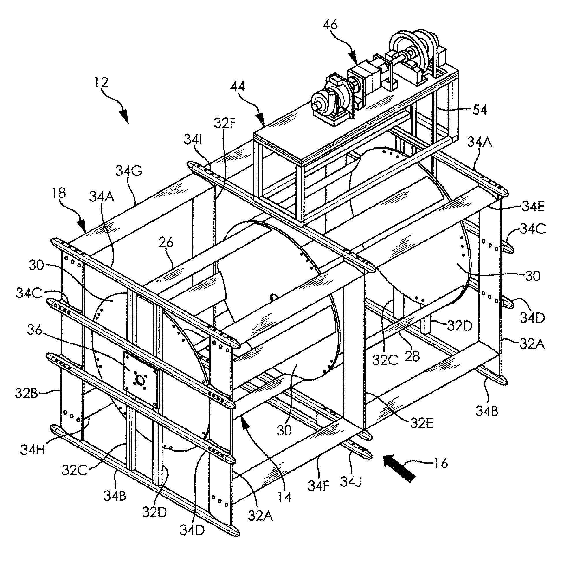
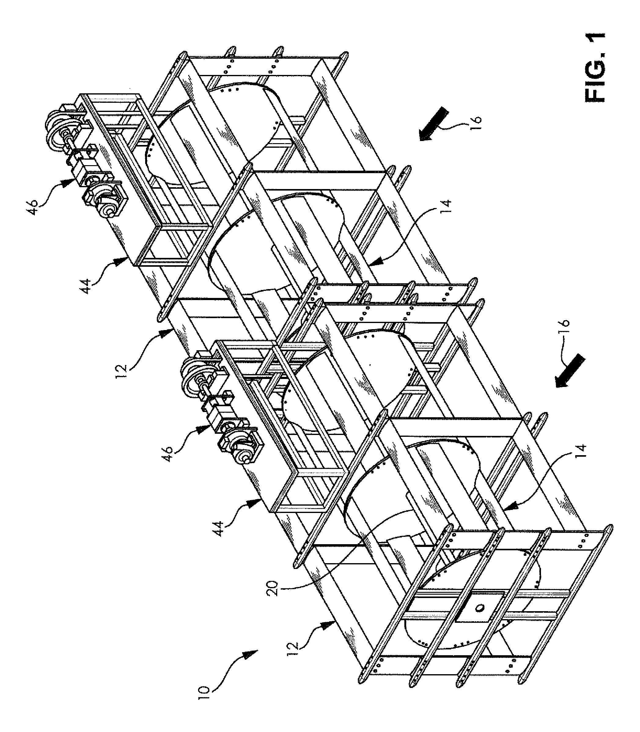
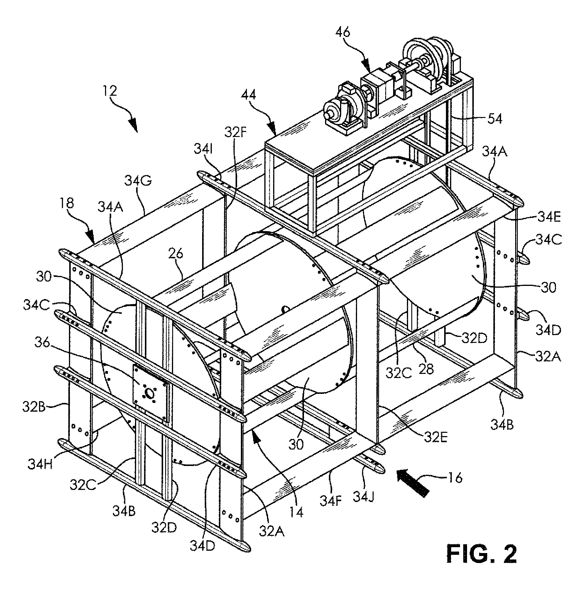
[0030]FIG. 1 illustrates a horizontal-axis hydrokinetic water turbine system 10 configured to be placed in a flowing stream of water according to one embodiment of the present invention. The illustrated hydrokinetic water turbine system 10 includes two water turbine assemblies 12 each having a horizontal axis water wheel or rotor 14 but it is noted that the hydrokinetic system 10 can alternatively have any other quantity of water turbine assemblies 12. The illustrated first and se...


PUM


Abstract

A hydrokinetic water turbine system includes a frame structure, first and second shafts rotatably supported by the frame structure, and first and second rotors secured to the first and second shafts respectively and each having a plurality of spaced-apart blades so that the flowing stream of water revolves the first and second rotors about a central axis of the first and second shafts respectively. The first and second shafts are horizontally-disposed and coaxial and the first and second rotors are adapted to rotate in opposite directions. The blades are hollow and filled with a foam material to reduce weight and increase buoyancy. The frame structure is a substantially rectangular and open frame structure and includes frame members adapted to reduce a coefficient of drag of the frame structure. The frame members can be hollow and filled with a foam material to reduce weight and increase buoyancy.

Description

CROSS-REFERENCE TO RELATED APPLICATIONS[0001]Not ApplicableSTATEMENT REGARDING FEDERALLY SPONSORED RESEARCH[0002]Not ApplicablePARTIES TO A JOINT RESEARCH AGREEMENT[0003]Not ApplicableREFERENCE TO APPENDIX[0004]Not ApplicableFIELD OF THE INVENTION[0005]The field of the present invention generally relates to apparatus that convert the movement of fluid into rotational mechanical motion for the generation of mechanical power or other useful purposes and, more particularly, to hydrokinetic water turbines that harness flowing water such as in rivers, streams, canals, industrial outflows, and the like for the generation of mechanical power or other useful purposes.BACKGROUND OF THE INVENTION[0006]First attempts at harnessing water as a source of energy was through waterwheels used for grinding, pumping, and driving various types of equipment. Some accounts suggest waterwheels were first used as long as 4,000 years ago. These water wheels used either the elevation change across the wheel ...

Claims


Application Information

Patent Timeline
Patent Type & Authority Patents(United States)
IPC IPC(8): F03B13/10F03B13/12
CPCF03B17/062F03B17/065F05B2240/221F05B2240/40F05B2260/72Y02E10/28Y02E10/20
Inventor RAJADHYAKSHA, VIKRAM V.HUFF, ROGER SAMCHERIAN, MOOKENCHERIL P.
Owner DLZ
Why Eureka
Try Eureka