Steering apparatus for a vehicle

a steering apparatus and vehicle technology, applied in the direction of steering devices, cycle equipments, frictional rollers based transmissions, etc., can solve the problems of high cost of external threading of stem pipes to receive such plural nuts, and achieve the reduction of the distance between the stem pipe and the upper bearing, the number of components required for assembling the steering apparatus, and the cost of the threading process.

Active Publication Date: 2013-09-10
HONDA MOTOR CO LTD
View PDF7 Cites 2 Cited by
  • Summary
  • Abstract
  • Description
  • Claims
  • Application Information

AI Technical Summary

Benefits of technology

[0024]According to the first aspect of the present invention, the fastening bolt is threaded into the internally threaded surface on the upper portion of the stem pipe, thereby fixing the top bridge. Since the top bridge is fixed with the step of the fastening bolt by reducing a diameter of the pipe insertion hole with the stem pipe slot-tightening mechanism, the fastening bolt is prevented from loosening. Since no conventional double nut structure is required for assembling the steering apparatus, the number of components required for assembling the steering apparatus is reduced. In addition, as the outer circumferential surface of the stem pipe does not need to be externally threaded, and only required to be internally threaded at an upper inner portion thereof, the cost of the threading process is lowered.
[0025]Since according to the present invention, a conventional double nut structure is not required, the top bridge can be positioned closely to the upper bearing, and the distance by which the stem pipe projects from the upper bearing can be reduced. Also, since the bending moment is reduced, the wall thickness of the stem pipe can be reduced.
[0026]According to the second aspect of the present invention, since no preloading nut is required to be provided between the upper bearing and the top bridge, the upper bearing and the top bridge can be positioned closely to each other. A length of the stem pipe interconnecting the top bridge and the upper bearing can be shortened, and the bending moment applied to the stem pipe can be reduced. Therefore, since a wall thickness and a length of the stem pipe can be reduced, the weight of the stem pipe can also be reduced.
[0027]According to the third aspect of the present invention, similar to the second aspect, since no preloading nut is required to be provided between the upper bearing and the top bridge, the upper bearing and the top bridge can be positioned closely to each other. The stem pipe interconnecting the top bridge and the upper bearing can be shortened, and the bending moment applied to the stem pipe can be reduced. Therefore, since a wall thickness and a length of the stem pipe can be reduced, the weight of the stem pipe can also be reduced.
[0028]According to the fourth aspect of the present invention, the stem pipe is firmly tightened and supported by the stem pipe slot-tightening mechanism, and the step is tightened when the stem pipe is reduced in diameter under compressive forces. Only a tightening force required to keep the fastening bolt from loosening is applied to the fastening bolt.
[0029]In other words, since the fastening bolt firmly supports the stem pipe which requires a greater tightening force, and the fastening bolt is tightened by only a tightening force required to keep the fastening bolt from loosening, the step of the fastening bolt does not need to be more rigid than necessary.

Problems solved by technology

Furthermore, since the stem pipe (5) needs to be externally threaded for installing the two nuts (17A, 17B) thereon, the cost of externally threading the stem pipe to receive such plural nuts is high.

Method used


Image

  • Steering apparatus for a vehicle
  • Steering apparatus for a vehicle
  • Steering apparatus for a vehicle

Examples


Embodiment Construction

[0040]An embodiment of the present invention will now be described, with reference to the drawings. Throughout this description, relative terms like “upper”, “lower”, “above”, “below”, “front”, “back”, and the like are used in reference to a vantage point of an operator of the vehicle, seated on the driver's seat and facing forward. It should be understood that these terms are used for purposes of illustration, and are not intended to limit the invention.

[0041]An illustrative embodiment of the present invention is described below with reference to the accompanying drawings.

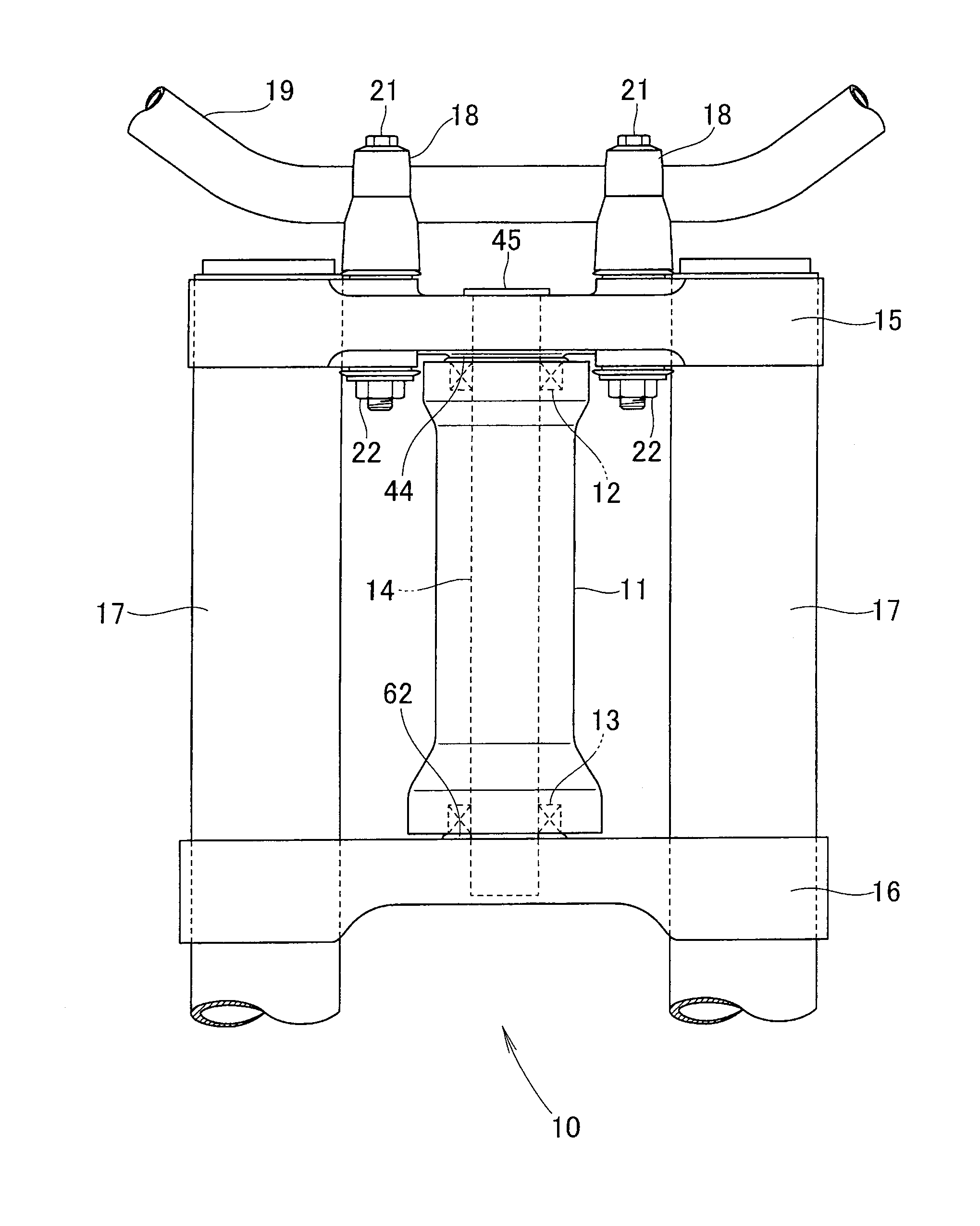
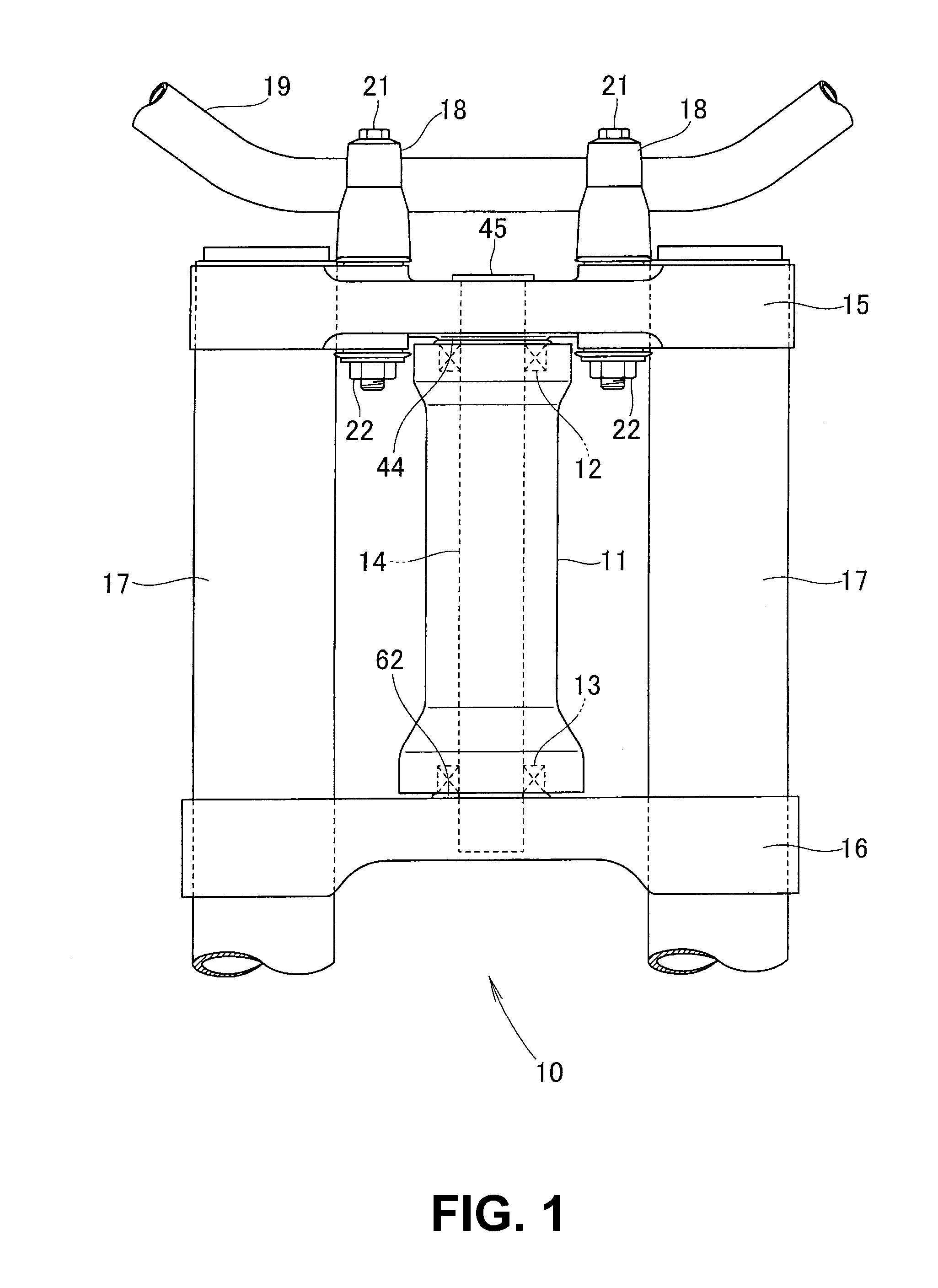
[0042]As shown in FIG. 1, a steering apparatus 10 for a vehicle includes a stem pipe 14 pivotally mounted in a head pipe 11 by upper and lower bearings 12, 13. A top bridge 15 and a bottom bridge 16 are mounted respectively on upper and lower ends of the stem pipe 14. Front fork members 17 are mounted on the top bridge 15 and the bottom bridge 16. A steering handle 19 is mounted on the top bridge 15 by handle hold...


PUM


Abstract

A steering apparatus for a vehicle includes a stem pipe disposed in a head pipe by upper and lower bearings interposed therebetween, a seal member for covering the upper bearing, and bottom and top bridges mounted on lower and upper ends of the stem pipe, respectively. A single fastening bolt, having a step formed between a head and a threaded surface thereof, is fitted in a pipe insertion hole of the top bridge and the upper threaded portion of the stem pipe. The stem pipe is firmly tightened and supported by a stem pipe slot-tightening mechanism of the top bridge. The fastening bolt is tightened by only a tightening force required to keep the fastening bolt from loosening. Also, a number of components required for the inventive steering apparatus is reduced, since an additional component, previously used for preventing loosening of a fastening bolt, is made unnecessary.

Description

CROSS-REFERENCE TO RELATED APPLICATIONS[0001]The present invention claims priority under 35 USC 119 based on Japanese patent application No. 2009-124178, filed on May 22, 2009. The entire subject matter of this priority document, including specification claims and drawings, is incorporated by reference herein.BACKGROUND OF THE INVENTION[0002]1. Field of the Invention[0003]The present invention relates to a steering apparatus for a vehicle. More particularly, the present invention relates to a steering apparatus for a vehicle, having a stem pipe pivotally mounted in a head pipe by upper and lower bearings, and secured with a top bridge using a single fastening bolt.[0004]2. Description of the Background Art[0005]There is a known steering apparatus for a vehicle, which has a stem pipe as an essential component thereof pivotally mounted in a head pipe by upper and lower bearings, mounted on the vehicle, such as, a two-wheeled motorcycle or the like. An example of such steering apparatu...

Claims


Application Information

Patent Timeline
Patent Type & Authority Patents(United States)
IPC IPC(8): B62K21/02B62K21/04B62K21/06
CPCB62K21/06B62K21/04
Inventor MORI, YOTAROUCHIYAMA, MIKIOGOGO, KAZUHIKO
Owner HONDA MOTOR CO LTD
Why Eureka
Try Eureka