Auxiliary locking drive for a motor vehicle lock

a technology for auxiliary locking and motor vehicles, which is applied in the field of auxiliary locking drive for motor vehicles, can solve the problems of low weight and achieve the effect of reducing the amount of installation space and the weight of the auxiliary locking driv

Active Publication Date: 2013-09-10
BROSE SCHLIESSSYSTEME GMBH & CO KG
View PDF18 Cites 12 Cited by
  • Summary
  • Abstract
  • Description
  • Claims
  • Application Information

AI Technical Summary

Benefits of technology

[0012]Therefore, a primary object of the present invention is to embody and develop the known auxiliary locking drive such that the amount of installation space required and the weight of the auxiliary locking drive are reduced.
[0014]First of all, it is important that, by providing the auxiliary locking drive with a feed gear mechanism which is made as spindle-nut gearing to produce a linear driving motion, this leads to a minimum installation space requirement. Furthermore, this arrangement can be implemented with a minimum number of components, and additionally, leads to a low weight.
[0017]In especially preferred configurations, the auxiliary locking drive in accordance with the invention can be easily designed or parameterized for the respective application. Different applications can require specifically different forces, speeds and feeds; this leads accordingly to different drive motors, intermediate gearing or feed gear mechanisms. Depending on the configuration, the drive housing and optionally the end piece of the Bowden cable must be adapted. This is especially easily possible by a telescoping configuration of the parts of the drive housing.
[0018]In accordance with further preferred embodiments, there is a lengthwise guide which is located parallel to the spindle and on which the spindle nut runs and there is a second spindle which is coupled to the drive shaft of the drive motor and which has a second spindle nut thread. These measures serve to prevent jamming of the spindle nut relative to the spindle even when the coupling of the core of the Bowden cable relative to the axis of the spindle is coupled off-center to the feed nut.

Problems solved by technology

Furthermore, this arrangement can be implemented with a minimum number of components, and additionally, leads to a low weight.

Method used


Image

  • Auxiliary locking drive for a motor vehicle lock
  • Auxiliary locking drive for a motor vehicle lock
  • Auxiliary locking drive for a motor vehicle lock

Examples


Embodiment Construction

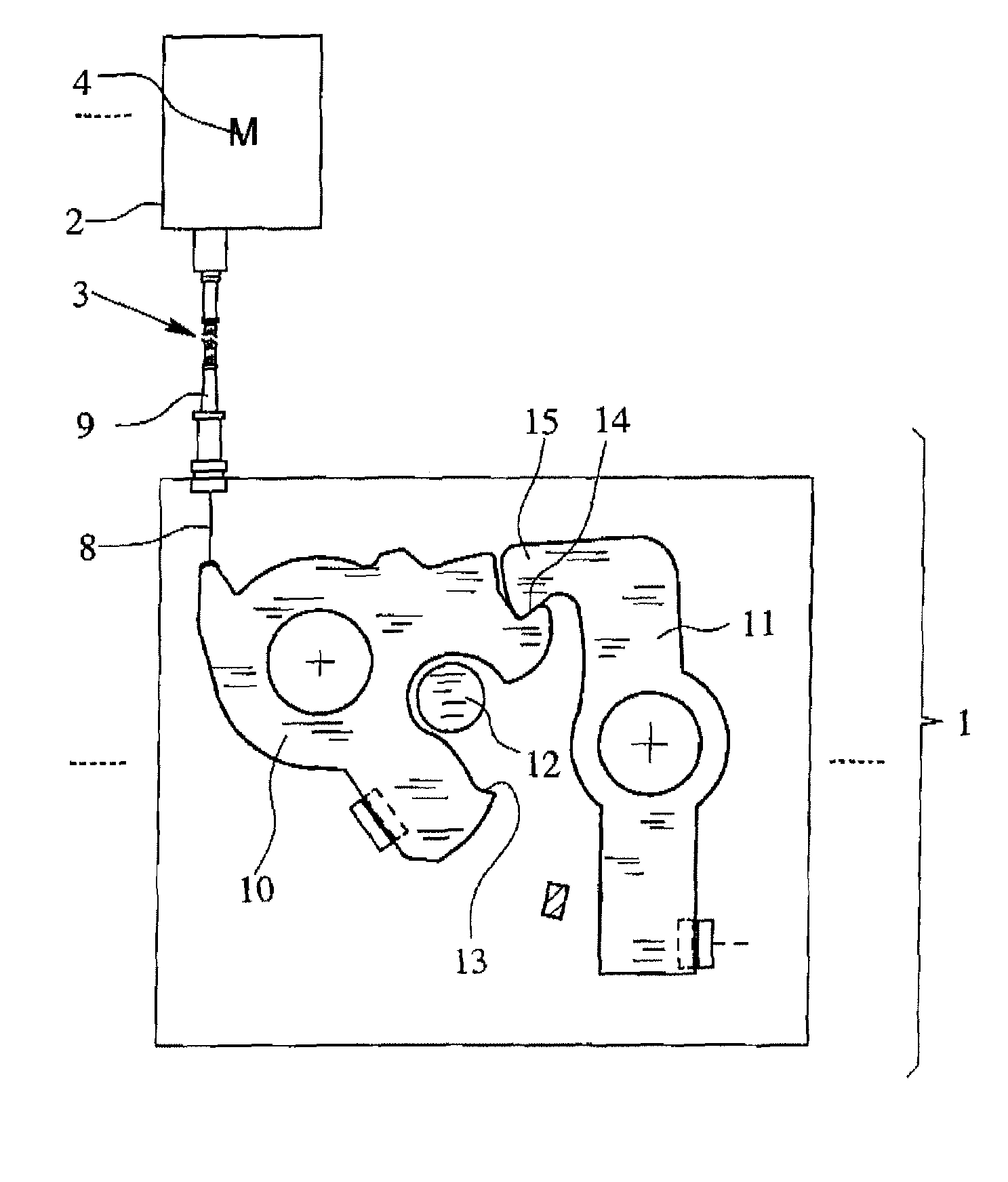
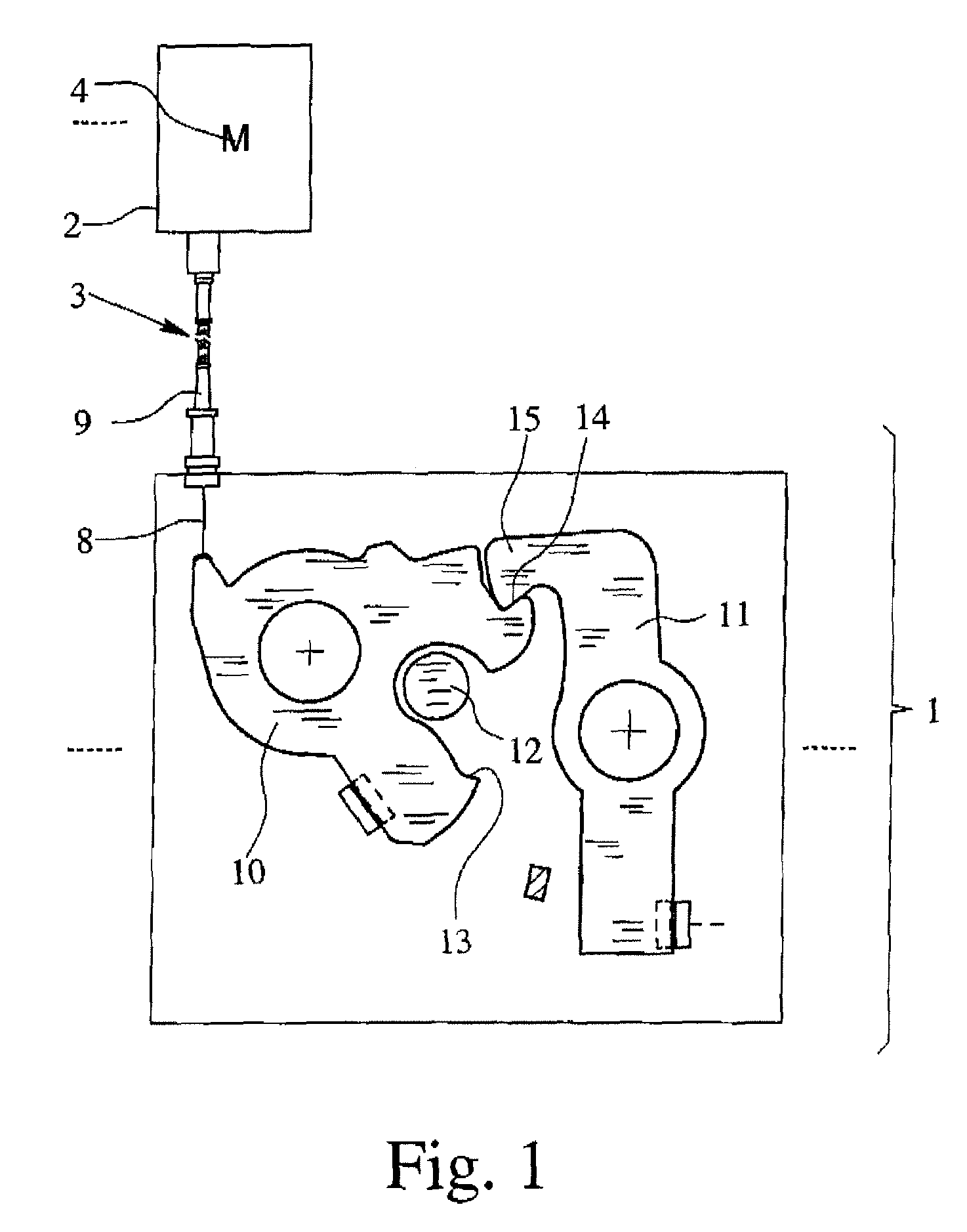
[0026]The structure of an auxiliary locking drive in accordance with the invention which is shown in FIG. 1 applies to all the embodiments shown in FIGS. 2 to 4. This auxiliary locking drive is assigned to a vehicle lock 1. With respect to a broad understanding of the concept “motor vehicle lock” reference should be made to the Background part of this specification.

[0027]In all the illustrated embodiments, the auxiliary locking drive has its own drive housing 2 and is located separately from the vehicle lock 1 in the installed state. As can be seen in FIG. 1, the auxiliary locking drive is coupled to the vehicle lock 1 by way of a transmission means 3.

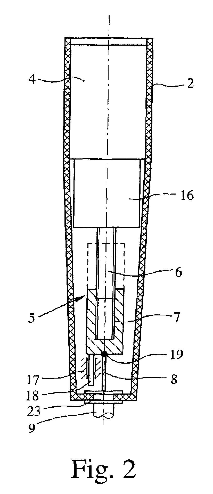
[0028]As can be seen in detail in FIGS. 2 to 4, the auxiliary locking drive has a drive motor 4 which, in the mounted state, is able to produce a linear driving motion that is transmitted to the vehicle lock 1 by way of the transmission means 3. This linear driving motion allows the vehicle lock 1 to be transferred from the half-locked...


PUM


Abstract

An auxiliary locking drive for a motor vehicle lock having its own drive housing and being located separate from the vehicle lock in the installed state. The auxiliary locking drive can be coupled to the vehicle lock by way of a transmission that transmits a linear driving motion produced by a drive motor to the vehicle lock for transferring the vehicle lock from the half-locked state into the main locked state by the driving motion. The auxiliary locking drive, for producing the linear driving motion, has a feed gear mechanism which is connected downstream of the drive motor and is made as a spindle-spindle nut gearing with a spindle and a spindle nut.

Description

BACKGROUND OF THE INVENTION[0001]1. Field of Invention[0002]The invention relates to an auxiliary locking drive for a motor vehicle lock having its own drive housing and being located separately from the vehicle lock in the installed state, being coupled to the vehicle lock by way of a transmission, having a drive motor, and in the mounted state, the drive motor producing a linear driving motion that is transmitted to the vehicle lock by way of the transmission so that the vehicle lock can be transferred from a half-locked state into a main locked state by the driving motion.[0003]2. Description of Related Art[0004]Here, the expression motor vehicle lock is defined as all types of door / hood / trunk or hatch locks.[0005]The vehicle lock is equipped with conventional latching elements, a latch and a ratchet, the ratchet keeping the latch in the main locked position and in the half-locked position. The ratchet is then in the engaged state. The latch can be moved into retaining engagement...

Claims


Application Information

Patent Timeline
Patent Type & Authority Patents(United States)
IPC IPC(8): E05C3/06
CPCE05B81/20E05B81/25E05B79/20E05B81/38Y10T292/1082Y10T70/5889
Inventor BETTIN, AXELBUEDDING, GREGORBROSE, SIMONLANGFERMAN, MICHAEL
Owner BROSE SCHLIESSSYSTEME GMBH & CO KG
Why Eureka
Try Eureka