Network connector structure

a network connector and connector technology, applied in the direction of coupling device connection, coupling device details, printed circuits, etc., can solve the problems of wasting precious installation space on the motherboard, and achieve the effect of saving precious installation space and enhancing the stability of the network connector

Inactive Publication Date: 2013-09-10
CHANG NAI CHIEN
View PDF11 Cites 13 Cited by
  • Summary
  • Abstract
  • Description
  • Claims
  • Application Information

AI Technical Summary

Benefits of technology

[0005]Therefore, it is a primary objective of the present invention to provide an improved network connector structure with the functions of encoding and decoding network signals by a network connector without requiring the installation of any additional network integrated circuit on a motherboard of an electronic device.
[0007]Compared with the prior art, the present invention has the following effects. The network connector has a built-in network integrated circuit, so that the motherboard no longer requires any installation of additional network integrated circuits to encode / decode the network signal. In other words, it is not necessary to reserve any wiring space on the motherboard for installing the network integrated circuit, so as to save precious installation space on the motherboard. Further, the filter element and the network integrated circuit are integrated into a single network connector, so that the signal compatibility can be tested and calibrated during the manufacture, and the stability of the network connector can be enhanced.

Problems solved by technology

However, the installed connectors occupy much space on the motherboard, so that the installation of one or more network integrated circuits on the motherboard will waste much precious installation space on the motherboard.

Method used


Image

  • Network connector structure
  • Network connector structure
  • Network connector structure

Examples


Embodiment Construction

[0016]The technical contents of the present invention will become apparent with the detailed description of preferred embodiments accompanied with the illustration of related drawings as follows. It is noteworthy that the drawings are provided for the purpose of illustrating the present invention only, but not intended for limiting the scope of the invention.

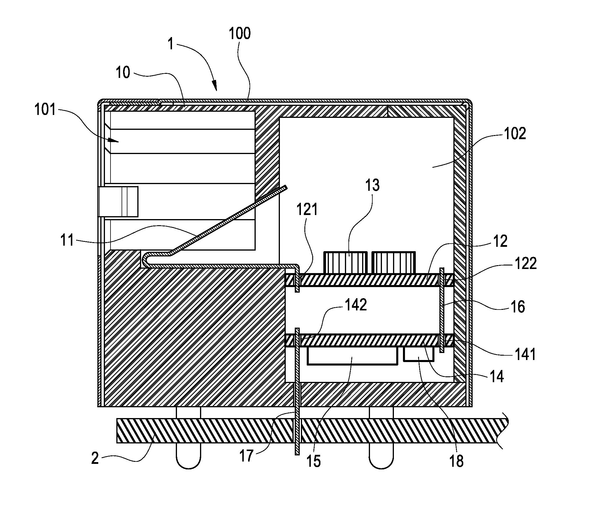
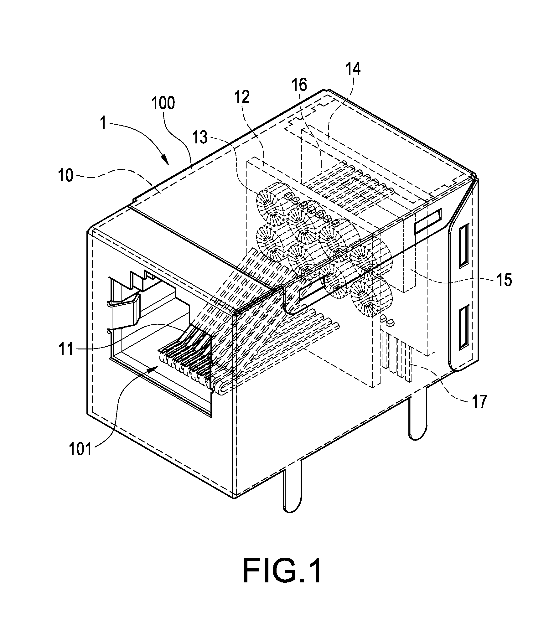
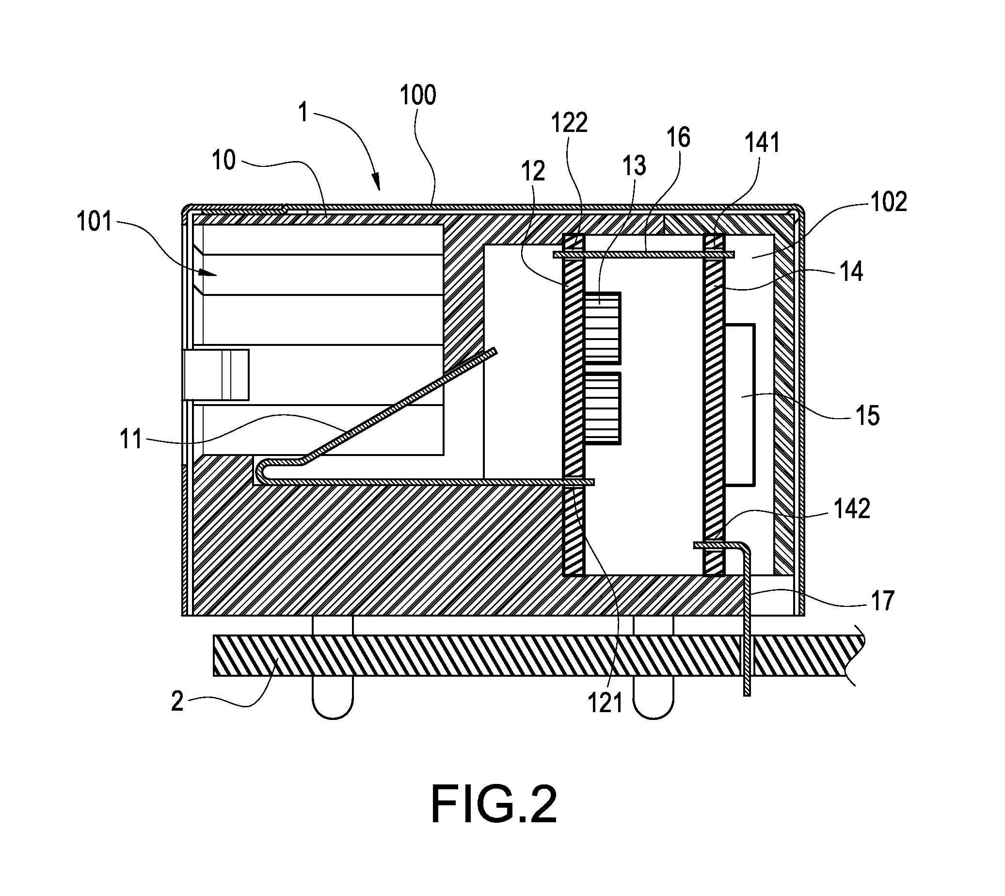
[0017]With reference to FIGS. 1 and 2 for a perspective view and a cross-sectional view of a network connector in accordance with the first preferred embodiment of the present invention respectively, the network connector 1 comprises an insulating body 10, and a port 101 inwardly formed at a front-end side of the insulating body 10 and having a containing space 102 formed in the insulating body 10.

[0018]The network connector 1 further includes a first circuit board 12 and a second circuit board 14 installed in the containing space 102 of the insulating body 10. In the figures, the first circuit board 12 and the second circuit bo...


PUM


Abstract

A network connector structure includes an insulating body having a port inwardly formed at a front-end surface of the insulating body, a containing space formed in the insulating body insulating body, and a first circuit board and a second circuit board parallely installed and electrically coupled to each other. A plurality of connecting terminals and a plurality of filter elements are electrically coupled to the first circuit board, and at least one network integrated circuit and a plurality of soldered terminals are electrically coupled to the second circuit board. The network connector is electrically coupled to an external transmission line through the plurality of connecting terminals, and electrically coupled to a motherboard of an external electronic device through the plurality of soldered terminals, so that the network integrated circuit inside the network connector provide network signal encoding / decoding functions directly.

Description

FIELD OF THE INVENTION[0001]The present invention relates to connectors, in particular to a network connector.BACKGROUND OF THE INVENTION[0002]As the electronic industry blooms, various electronic devices are continuously developed and introduced in our life. In order to input a control instruction to control the electronic devices or transmit data between the electronic devices, most electronic devices are equipped with a plurality of connectors installed on a motherboard. Signals transmitted and received by various connectors are encoded / decoded by at least one integrated circuit (IC) installed on a motherboard. For example, a RJ-45 network connector is electrically coupled to a motherboard of an electronic device, and an external network circuit is connected for receiving external network signals. After the network connector receives a network signal, the network signal is transmitted to the motherboard, and after a network integrated circuit installed on the motherboard is used ...

Claims


Application Information

Patent Timeline
Patent Type & Authority Patents(United States)
IPC IPC(8): H01R13/66
CPCH01R13/6658H01R24/64H01R2107/00
Inventor CHANG, NAI-CHIEN
Owner CHANG NAI CHIEN
Why Eureka
Try Eureka