Method and device for capacitive sensing

a capacitive sensing and capacitive technology, applied in the field of capacitive sensing devices and methods, can solve the problem that the sensing can be easily affected, and achieve the effect of higher differen

Active Publication Date: 2013-09-10
EGALAX EMPIA TECH INC
View PDF9 Cites 17 Cited by
  • Summary
  • Abstract
  • Description
  • Claims
  • Application Information

AI Technical Summary

Benefits of technology

[0015]The present invention also discloses a capacitive sensing device, comprising: a plurality of first conductive lines electrically isolated from each other; a plurality of second conductive lines electrically isolated from each other, wherein the first and second conductive lines are electrically isolated from and stacked on one another forming a plurality of intersecting points; and a plurality of electrical conductors electrically isolated from each other, the electrical conductors respectively crossing the first and second conductive lines and positioning around the intersecting points, wherein the first and second conductive lines and the electrically conductors are electrically isolated from one another, thereby when a plurality of objects capactively or contact coupled with at least one of the first and second conductive lines and the electrical conductors, a sensing unit sensing a compound value of the capacitive couplings between the objects and the coupled first and second conductive lines and electrical conductors, providing a higher difference for identifying and eliminating ghost coordinates that are coupled with the objects.

Problems solved by technology

However, the magnitudes of d1˜d4 are too small to make use, and sensing can be easily affected by noises, thus multi-touch operations are often mistakenly determined.

Method used


Image

  • Method and device for capacitive sensing
  • Method and device for capacitive sensing
  • Method and device for capacitive sensing

Examples


Embodiment Construction

[0037]The present invention is described by the following specific embodiments. Those with ordinary skills in the arts can readily understand the other advantages and functions of the present invention after reading the disclosure of this specification. The present invention can also be implemented with different embodiments. Various details described in this specification can be modified based on different viewpoints and applications without departing from the scope of the present invention. In order to illustrate the principles of the present invention, some elements are not drawn to scale, exaggerated or omitted for clarity.

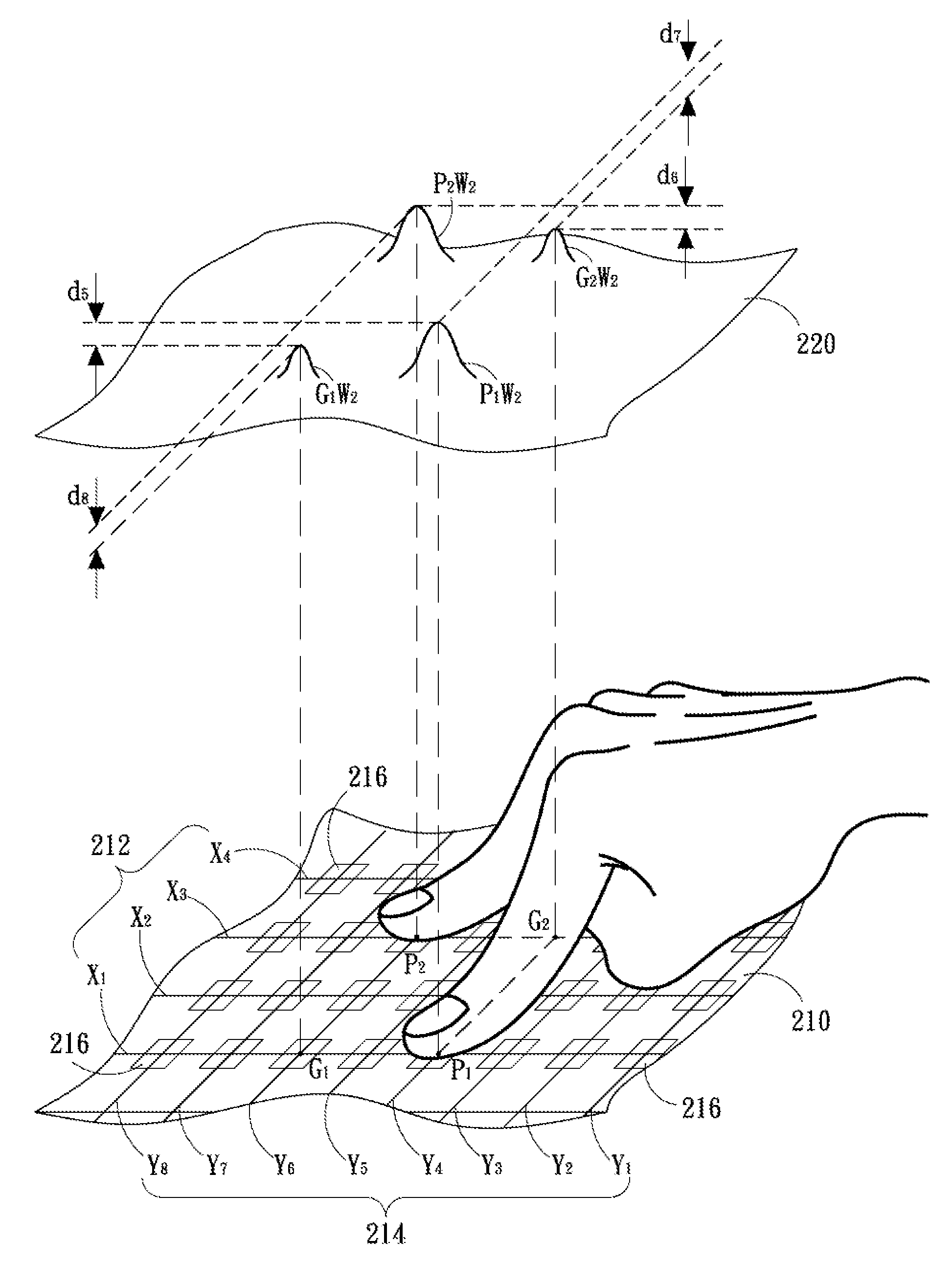
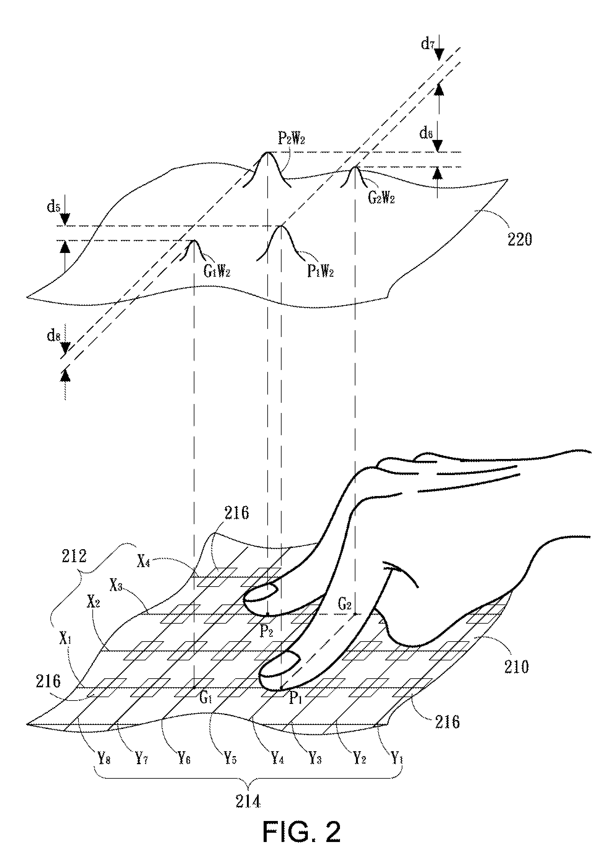
[0038]Referring to FIG. 2, a diagram depicting multi-touch operations and a capacitance image according to a preferred embodiment of the present invention is shown. A touch panel 210 has a plurality of first conductive lines 212 and a plurality of second conductive lines 214. The first and second conductive lines 212 and 214 are stacked on and electrically iso...


PUM


Abstract

The disclosed capacitive sensing device has first conductive lines, second conductive lines and electrical conductors. The first conductive lines are electrically isolated from each other, the second conductive lines are electrically isolated from each other and electrically isolated from and stacked with the first conductive lines to form numerous intersecting points, and the electrical conductors are electrically isolated from each other and correspondingly crossing the first and the second conductive lines and being around the intersecting points. Herein, the electrical conductors are electrically isolated from the first and second conductive lines. When an electrical signal is driven to a first conductive line, the first conductive line is capacitively coupled to the second conductive lines which intersecting mutually, and the electrical conductors crossing the first conductive line are respectively capacitively coupled to the first conductive line and the mutually intersecting second conductive lines to provide a higher compound capacitance.

Description

BACKGROUND OF THE INVENTION[0001]1. Field of the Invention[0002]The present invention relates to a touch device and method, and more particularly, to a capacitive sensing device and method.[0003]2. Description of the Prior Art[0004]Referring to FIG. 1, a diagram depicting a prior-art capacitive sensing device with multi-touch operations and a capacitance image is shown. A touch panel 110 has a plurality of first conductive lines 112 and a plurality of second conductive lines 114. The first and second conductive lines are perpendicularly stacked on and electrically isolated from each other. When a sensing signal (not shown) is input to one of the first conductive lines 112, it creates a plurality of capacitive coupling with all of the second conductive lines at intersecting points, thereby determining the electrical characteristics of the intersecting points based on the current or voltage on all of the second conductive lines. Each of the first conductive lines 112 are sequentially ...

Claims


Application Information

Patent Timeline
Patent Type & Authority Patents(United States)
IPC IPC(8): G06F3/045
CPCG06F3/044G06F3/04883G06F2203/04104G06F2203/04808G06F3/0445G06F3/0446
Inventor CHANG, CHIN-FU
Owner EGALAX EMPIA TECH INC
Why Eureka
Try Eureka