
Sand detector calibration

a technology of acoustic sand and detectors, applied in the field of acoustic sand detector calibration, can solve the problems of eroded walls, flowline failure, leakage of production fluid, etc., and achieve the effect of more accurate detetmination of sand amounts

Inactive Publication Date: 2013-09-17
GE OIL & GAS UK LTD
View PDF8 Cites 15 Cited by
  • Summary
  • Abstract
  • Description
  • Claims
  • Application Information

AI Technical Summary

Benefits of technology

The present invention provides a method to better detect the amount of sand in fluid extraction wells, which can help identify equipment damage and potential flowline collapse. It also allows for real-time adjustments to calibration. This information helps well operators make changes to increase equipment life and the hydrocarbon reservoir.

Problems solved by technology

The impact of these particles on the walls of production fluid flowlines, which carry the fluid to the surface, is known to erode the walls.
If this erosion is unchecked, the flowline may fail, and leak production fluid to the surrounding region.
However, the output of such detectors does not give a clear indication of the levels of sand within the flow, since not all the sand will create a detectable impact in the vicinity of the detector.
However, proper calibration by the manufacturers is difficult due to a number of factors, for example: different types of sand, e.g. with differing grain sizes or density; different environments, e.g. pipe differences leading to differing levels of acoustic signal damping, or internal fluid differences, or background noise; and imprecise knowledge of the exact location where sand hits the wall, e.g. due to flow properties and sand type.
In addition, the above variables may not only be hard to predict, but may also change substantially over the life of a production field, making the measurement from the detectors even more inaccurate.

Method used


Image

  • Sand detector calibration
  • Sand detector calibration

Examples


Embodiment Construction

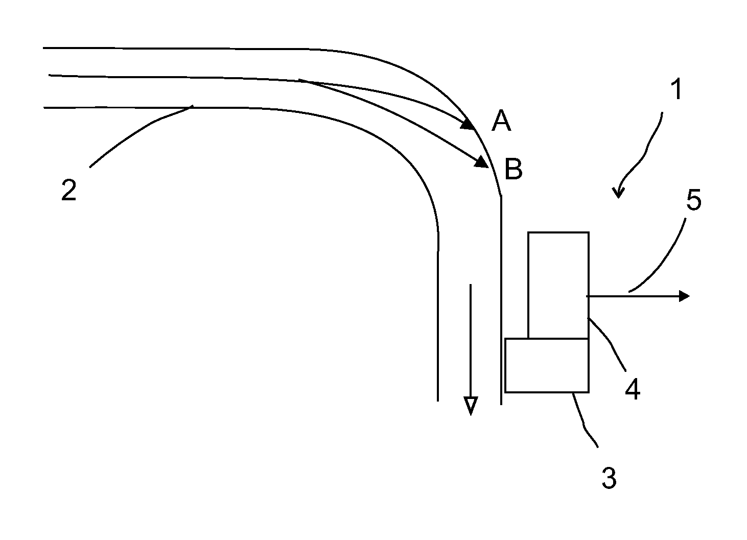
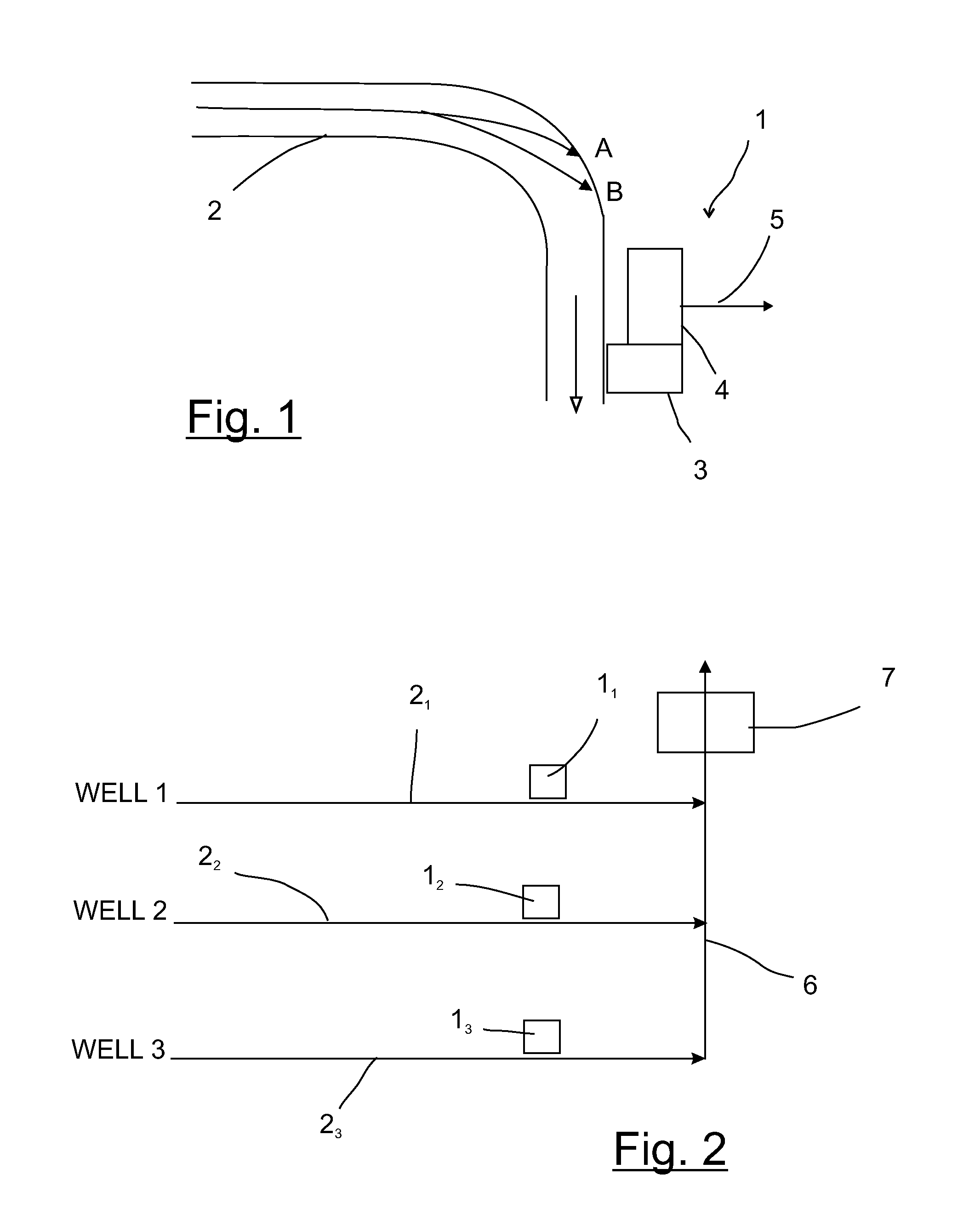
[0018]FIG. 1 schematically shows an acoustic sand detector 1 deployed at a flowline 2, wherein the fluid flow direction is from the leftmost end to the lower right end as shown by the arrow. The acoustic sand detector 1 comprises an acoustic sensor 3, which picks up acoustic signals, and transducer 4. The acoustic signals received by sensor 3 are fed to the transducer 4, which converts the acoustic signals into electrical output signals 5. Such acoustic sand detectors 1 are known in the art.

[0019]FIG. 1 also shows possible flow paths for two sand particles A and B, which as a result of the complex fluid flow within flowline 2 are caused to impact on the side of the flowline 2. As shown, the flowline includes an elbow, and the impacts are likely to occur in the vicinity of the elbow as shown. Assuming that the particles A and B are of similar constitution, mass and speed at the time of impact with the side of the flowline 2, it is apparent that the impact of particle B will cause a g...


PUM

PropertyMeasurementUnit
distanceaaaaaaaaaa
velocityaaaaaaaaaa
flow velocityaaaaaaaaaa

Abstract

A method of operating an acoustic sand detector deployed at a flowline within a flow system, the detector comprising an acoustic sensor and functioning to produce electrical output signals in dependence on acoustic signals detected by the acoustic sensor, the acoustic signals being at least partially produced by the impact of sand particles within the flow on an object is provided. The method comprises estimating the location of particle impacts on the flowline; and weighting the output signals according to the distance between the estimated location and the detector location.

Description

BACKGROUND OF THE INVENTION[0001]1. Field of the Invention[0002]Embodiments of the present invention relate to methods of operating and calibrating acoustic sand detectors, and a method of determining the life expectancy of a flowline. Embodiments of the present invention are particularly suitable for implementation with production flowlines of hydrocarbon wells, for example subsea hydrocarbon production wells.[0003]2. Description of the Prior Art[0004]Production fluid from fluid extraction wells, for example underwater hydrocarbon extraction wells, typically have solid particles such as sand entrained within it. The impact of these particles on the walls of production fluid flowlines, which carry the fluid to the surface, is known to erode the walls. If this erosion is unchecked, the flowline may fail, and leak production fluid to the surrounding region.[0005]The level of erosion will be dependent on various factors, with the most important being the quantity of sand entrained with...

Claims


Application Information

Patent Timeline
Patent Type & Authority Patents(United States)
IPC IPC(8): G01N33/00E21B47/10
CPCE21B47/101G01F1/666G01F1/74G01N29/4463G01N29/046G01N2291/02836G01N2291/02408G01N2291/02416E21B47/107
Inventor ELLSON, NICHOLAS JOSEP
Owner GE OIL & GAS UK LTD
Learn More