Digitally forming a dental model for fabricating orthodontic laboratory appliances

a laboratory appliance and digital technology, applied in the field of digital orthodontics, can solve the problems of inconvenience for patients, delay in transporting the physical dental model to the laboratory, and shipping costs

Inactive Publication Date: 2013-09-17
3M INNOVATIVE PROPERTIES CO
View PDF40 Cites 40 Cited by
  • Summary
  • Abstract
  • Description
  • Claims
  • Application Information

AI Technical Summary

Benefits of technology

[0049]Once the plaster model has been prepared, an orthodontic laboratory appliance can be manufactured using the plaster model as designated by block 120 in FIG. 1. Presently, there are many established appliance providers, such as commercial orthodontic laboratories, that routinely use a stone model to fabricate laboratory appliances as a service to the orthodontic professional. This is one advantage of the present invention, since an infrastructure currently exists in the market for the manufacturing of laboratory appliances from physical dental models such as the models 10,16 in the embodiments exemplified above.
[0050]FIG. 9 illustrates an exemplary laboratory appliance (in this case, a retainer). In this figure, an appliance 30 is formed on the physical dental model 10,16. Appliance 30 includes a wire portion 32 which contacts the model teeth along with a plastic body 34 that contacts the model palate. In some embodiments, wire portion 32 is made from metal, such as stainless steel, and conforms closely with the tooth portions of model 10,16. Wire portion 32 is partially embedded in a plastic body 34, which can be made from a cold-cured acrylic polymer such as polymethylmethacrylate. Body 34 may alternatively be made from a soft polymer such as a silicone or a thermoformed polymer such as polycarbonate.
[0051]To form appliance 30, wire portion 32 is first shaped to conform to model 10,16. The shaping of wire portion 32 is typically a manual process performed by a technician, but may also be automated using robotic wire bending techniques, such as those disclosed in U.S. Pat. No. 6,612,143 (Butscher et al), U.S. Pat. No. 6,928,733 (Rubbert et al) and U.S. Pat. No. 7,076,980 (Butscher). Furthermore, the plastic pads that conform to the soft tissues of the patient may be fitted by applying a layer of uncured acrylic resin on the model 10,16 to form the plastic body 34. Wire portion 32 may then be embedded in body 34 prior to curing body 34. Alternatively, a thermoformed polymer may be contacted with model 10,16 and heat and pressure applied to embed wires 32 and form body 34. Excess plastic on body 34 may then be trimmed as desired to provide the appliance 30. Optionally, the appliance 30 includes other components, including springs, customized frameworks, pivots, beams, and other mechanical elements. The above processes may also take into account the articulation of model 10,16 with an opposing lower dental model (not shown) to properly configure appliance 30.
[0052]Other laboratory appliances, such as Hyrax appliances, Twin Block, Crozat appliances and others, use open or closed loop wire configurations and optionally include appliance sections that are welded or brazed together on physical dental model 10,16. Other orthodontic laboratory appliances and appliance fabrication methods known to those of skill in the art are possible and examples are described in chapter 2-3, 2-6, and 2-7 of Willison, Practical Guide to Orthodontic Appliances: a comprehensive resource from theory to fabrication, Tonawanda, N.Y., Great Lakes Orthodontics, 2004, as well as issued U.S. Pat. No. 2,531,222 (Kesling), U.S. Pat. No. 3,271,858 (Simmons), U.S. Pat. No. 3,994,068 (Goshgarian), U.S. Pat. No. 4,798,534 (Breads) and U.S. Pat. No. 4,976,614 (Tepper).Other Embodiments
[0053]The processes described in the foregoing may be entirely carried out within the office of an orthodontic professional. However, this need not be the case. In some embodiments, the digital data may be generated using a scanner at the office of an orthodontic professional or other service provider and then transmitted over the internet or some other electronic means to a remote location for processing. In some embodiments, the digital data is transmitted to a laboratory appliance fabricator.
[0054]Furthermore, the forming of the negative mold 2,4,14,18, preparation of the physical dental model 10,16, and fabrication of the laboratory appliance 30 may be completed in a remote location such as that of a laboratory appliance fabricator, after which the finished laboratory appliance is shipped back to the orthodontic professional. The physical dental model 10,16 may also be shipped back to the orthodontic professional if desired.

Problems solved by technology

While this workflow is effective, transporting the physical dental model to the laboratory incurs a delay as well as a shipping cost.
Moreover, the process of creating an alginate impression and pouring a stone model is time consuming for the staff of an orthodontic practice and is often unpleasant for the patient.

Method used


Image

  • Digitally forming a dental model for fabricating orthodontic laboratory appliances
  • Digitally forming a dental model for fabricating orthodontic laboratory appliances
  • Digitally forming a dental model for fabricating orthodontic laboratory appliances

Examples


example 1

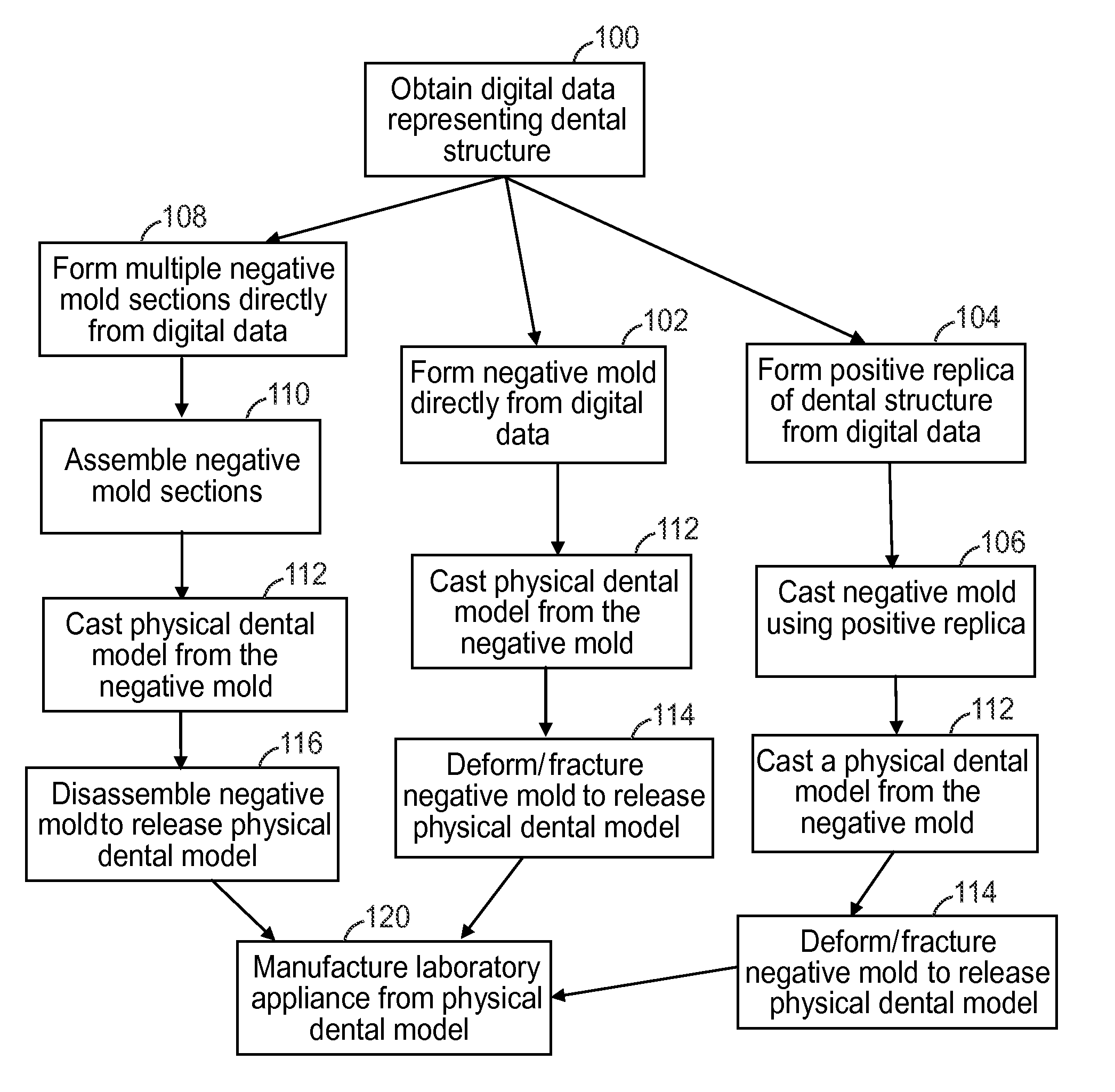
[0058]Raw digital data, representing a patient's lower dental arch with surrounding soft tissue, was obtained from an intraoral scan provided by Brontes Technologies, Inc. (Lexington, Mass.). The digital data set was then cleansed and surfaced using Raindrop Geomagic software to produce a clear 3D surface image of the dental structure. This surface was then offset to define a negative shell with an interior contour exactly matching the original dental structure. The negative shell, as represented by the digital data, was then printed using a VIPER brand SLA system from 3D Systems using ACCURA brand Si-40 photopolymer SLA material, also from 3D Systems. The printed negative shell was then used as a mold to cast a positive dental model using white orthodontic stone provided by Whip-Mix Corporation (Louisville, Ky.). Once cast, the stone model was allowed to set at room temperature for 1 hour. After the stone model was fully hardened, the negative mold and stone dental model were place...

example 2

[0059]The original digital data set from Example 1 was then used to print a second negative shell, this time using a low modulus resin. To form the low modulus shell, the digital data set was again refined and offset to produce a virtual digital shell structure. A physical shell based on the virtual shell was then printed using an EDEN 500V 3D printing machine from Objet Geometries, used with Fullcure 930 Series “TangoBlack” resin, also provided by Objet Geometries. To provide added strength, the shell thickness for this prototype was defined to be approximately 3 millimeters. Once again, the printed shell was used as a negative mold to cast a positive dental model using orthodontic stone as described in Example 1. After the model had set, the negative mold was flexibly removed from the cast stone dental model at room temperature with no apparent damage to the cast model. This example demonstrates that a rapid prototyping process can directly fabricate a negative mold that is suffic...

example 3

[0060]As in Example 1, a digital data set representing a dental structure was cleansed and surfaced. Instead of using the surface to define a negative mold object, however, the data set was used to define a virtual positive mold object or a replica of the dental structure. This data set was then used to print a positive mold using the VIPER brand SLA system and ACCURA brand Si-40 photopolymer SLA material mentioned above. After verifying the positive mold was accurate, a negative mold was formed over the positive mold using Z-DUPE brand duplication silicone provided by Henry-Schein Inc. (Melville, N.Y.) in conjunction with a cylindrical molding vessel, fully submerging the positive mold in the Z-DUPE material, and allowing the silicone to set for 2 hours. After the silicone negative mold was hardened, it was detached from the positive mold and subsequently used to cast the physical dental model out of orthodontic stone as carried out in Examples 1 and 2. The Z-DUPE matrix material w...


PUM


Abstract

The present invention provides a method that uses digital data, such as that obtained from an intraoral scanner, to fabricate a wide range of customized laboratory appliances. The digital data is used to form a negative mold, which is in turn used to make a physical dental model. The negative mold is configured such that it can be flexed, stretched, fractured or disassembled to release the physical dental model. The physical dental model is then used for fabricating an orthodontic laboratory appliance.

Description

CROSS REFERENCE TO RELATED APPLICATIONS[0001]This application is a national stage filing under 35 U.S.C. §371 of PCT / US2008 / 075658, filed Sep. 9, 2008, which claims priority to U.S. Provisional Application Ser. No. 60 / 975,687, filed Sep. 27, 2007, the disclosure of which is incorporated by reference in its / their entirety herein.BACKGROUND OF THE INVENTION[0002]1. Field of the Invention[0003]This invention relates to the area of digital orthodontics and more particularly to methods of using digital data to fabricate appliances.[0004]2. Description of the Related Art[0005]Orthodontics is the area and specialty of dentistry associated with the supervision, guidance and correction of malpositioned teeth into proper locations. Orthodontic treatment can be useful in correcting defects in a patient's bite (also called occlusion) along with promoting better hygiene and improving the overall aesthetics and health of the teeth.[0006]During the course of such treatment, an orthodontic professi...

Claims


Application Information

Patent Timeline
Patent Type & Authority Patents(United States)
IPC IPC(8): A61C13/00G06T19/00
CPCA61C7/00A61C7/002A61C13/0004B33Y80/00
Inventor PUTTLER, OLIVER L.KIM, SUNGHAN
Owner 3M INNOVATIVE PROPERTIES CO
Why Eureka
Try Eureka