Thread scheduling in chip multithreading processors

Active Publication Date: 2013-09-17
ORACLE INT CORP
View PDF10 Cites 14 Cited by
  • Summary
  • Abstract
  • Description
  • Claims
  • Application Information

AI Technical Summary

Benefits of technology

[0009]According to one aspect of one or more embodiments of the present invention, a computer system comprises an integrated circuit having a processing core fabricated therein, where the integrated circuit is c

Problems solved by technology

A thread may become blocked when the thread encounters a long-late

Method used


Image

  • Thread scheduling in chip multithreading processors
  • Thread scheduling in chip multithreading processors
  • Thread scheduling in chip multithreading processors

Examples


Embodiment Construction

[0026]An exemplary processor in accordance with one or more embodiments of the present invention is formed of one or more processing cores, each being configured to execute multiple threads. Such a processor is referred to as a “chip multithreading” processor. Thus, a chip multithreading processor has one or more processing cores fabricated on a single piece of silicon, where each processing core is configured to execute multiple threads as shown in FIG. 6 (showing the processing of 16 threads by a single chip multithreading processor versus (i) the processing of one thread in a single-threaded processor as shown in FIG. 7 and (ii) the processing of multiple threads in a processor having a single multithreaded processing core as shown in FIG. 8, where C represents a short-latency event and M represents a long-latency event).

[0027]Those skilled in the art will note that memory speeds have been increasing at a slower rate than processor speeds. Thus, typical processors may be stalled ...


PUM


Abstract

A thread scheduling technique for assigning multiple threads on a single integrated circuit is dependent on the CPIs of the threads. The technique attempts to balance, to the extent possible, the loads among the processing cores by assigning threads of relatively long-latency (low CPIs) with threads of relatively short-latency (high CPIs) to the same processing core.

Description

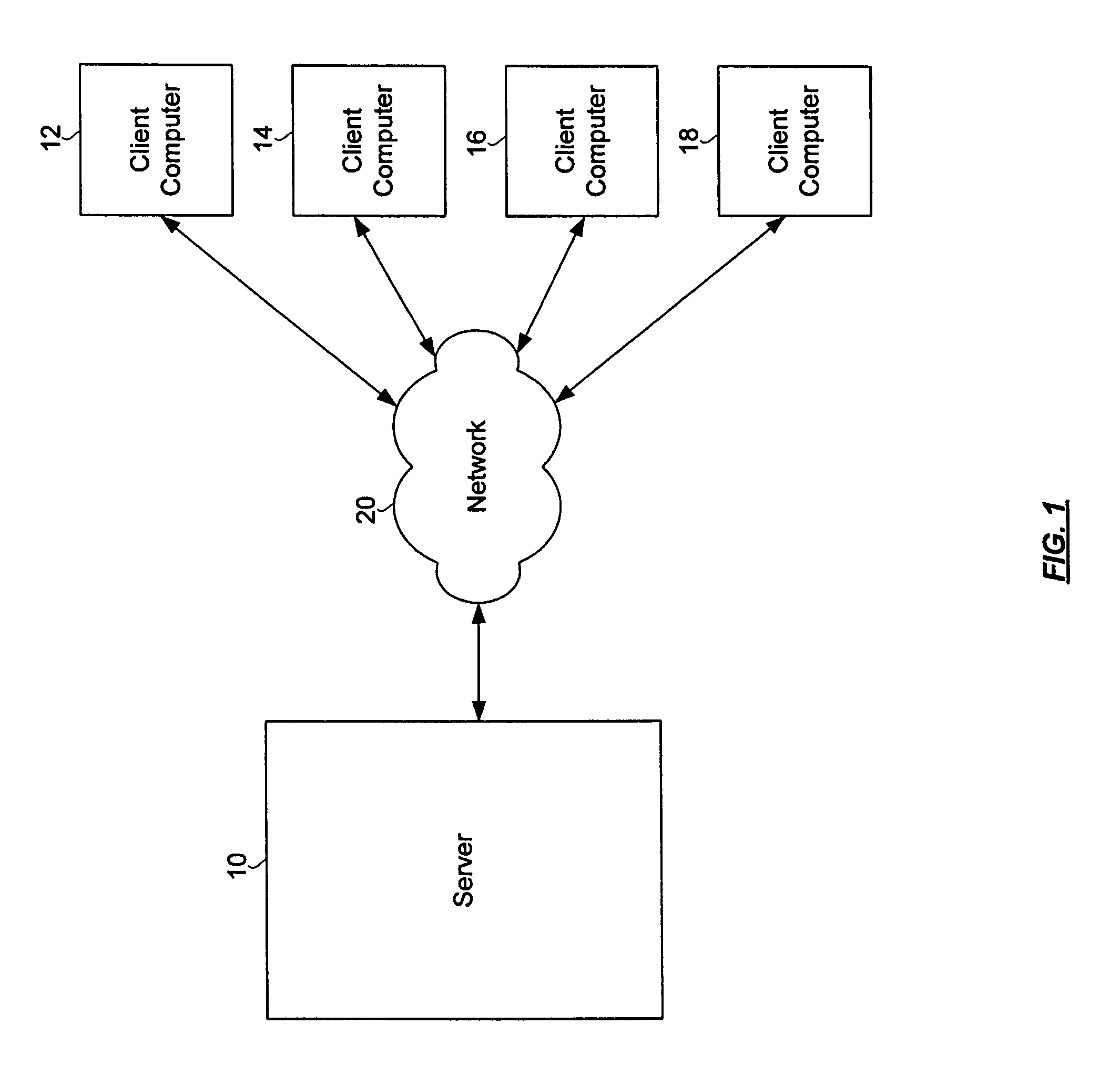
BACKGROUND OF INVENTION[0001]In a typical computer network, a server computer 10 services requests from and provides data to client computers 12, 14, 16, 18 that are connected to the server computer 10 over a network (e.g., the Internet) 20. The server computer 10 may be used to store data, programs, etc. for use by the client computers 12, 14, 16, 18. Those skilled in the art will recognize that the server computers 10 may also be used to manage and control the client computers 12, 14, 16, 18.[0002]In one example, an internet-based business may operate a server (or servers) to handle customer requests initiated at computer terminals located potentially thousands of miles away from the business's server(s). Each time a customer accesses the website of the business, an independent set of software instructions, i.e., a “thread,” is executed by a processor of the business's server(s) to provide requested data to the customer.[0003]In order to better meet increased networking demands, t...

Claims


Application Information

Patent Timeline
IPC IPC(8): G06F9/46
CPCG06F9/5083
Inventor SMALL, CHRISTOPHER A.NUSSBAUM, DANIEL S.FEDOROVA, ALEXANDRA
Owner ORACLE INT CORP
Why Eureka
Try Eureka