System for preventing condensation on refrigerator doors and frames

Active Publication Date: 2013-09-24
SUPERMARKET ENERGY TECH
View PDF20 Cites 28 Cited by
  • Summary
  • Abstract
  • Description
  • Claims
  • Application Information

AI Technical Summary

Benefits of technology

The present invention is a device that helps manage the energy consumption of a refrigerator by controlling the heating of the doors and frame, as well as fanning and lighting. It can communicate with sensors that detect humidity, temperature, movement, and water level. The control unit can also be controlled remotely using a command unit that communicates wirelessly with the control unit and can be connected to the internet for monitoring and control. The technical effect is efficient management of energy consumption for refrigerators, with the ability to control components remotely.

Problems solved by technology

Condensation on doors obstructs visibility of the products, while condensation that builds on the outer surface of the refrigerator frame causes unsafe conditions when it falls and pools on the floor.
These devices fail, however, to prevent condensation because the heater is not activated until after condensation is sensed.
This increases energy consumption because the humidity in the aisle is not always indicative of the conditions on the door surface, so condensation may not be imminent.
In this approach, the heaters are either constantly on or turned on unnecessarily.
This design causes expenditure of up to twice as much energy as necessary, the most wasteful case being when the door and frame heaters are never needed simultaneously.
The power usage of a failing fan motor may fluctuate for a period before its failure, and the power usage of all fan motors may spike after the failure.
This may cause unnecessary temperature fluctuations that can lead to condensation, and also affects the refrigerator's energy efficiency.
Additionally, fans are typically installed near the bottom of the refrigerator, where they are susceptible to water damage if the refrigerator floods during cleaning or a problem.
While this approach conserves some energy, it also shortens the life of refrigerator lights.
Detecting the specific location of an electrical failure is frustrating and time consuming due to the need to test each separate device.
Balancing the system becomes tedious.
Hardwiring the various sensors to the control box is problematic as it increases the time needed to install anti-sweat controllers.
Additionally, the wires can be accidentally cut which results in a non-functioning anti-sweat controller which may require a qualified repairman to fix.
Additionally, anti-sweat controllers are hardwired into the local power source, which results in difficult access for repair and replacement because the anti-sweat controllers must be unwired each time they are removed and rewired each time they are reinstalled.
If the anti-sweat controller breaks, the fact that the system is integral with the local power source may cause the shopkeeper to be unable to set the system to keep the heaters on until a qualified repairman fixes the problem.
Further, the dismantling and reconstruction cause safety issues while obstructing customer access to the refrigerators.

Method used


Image

  • System for preventing condensation on refrigerator doors and frames
  • System for preventing condensation on refrigerator doors and frames
  • System for preventing condensation on refrigerator doors and frames

Examples


Embodiment Construction

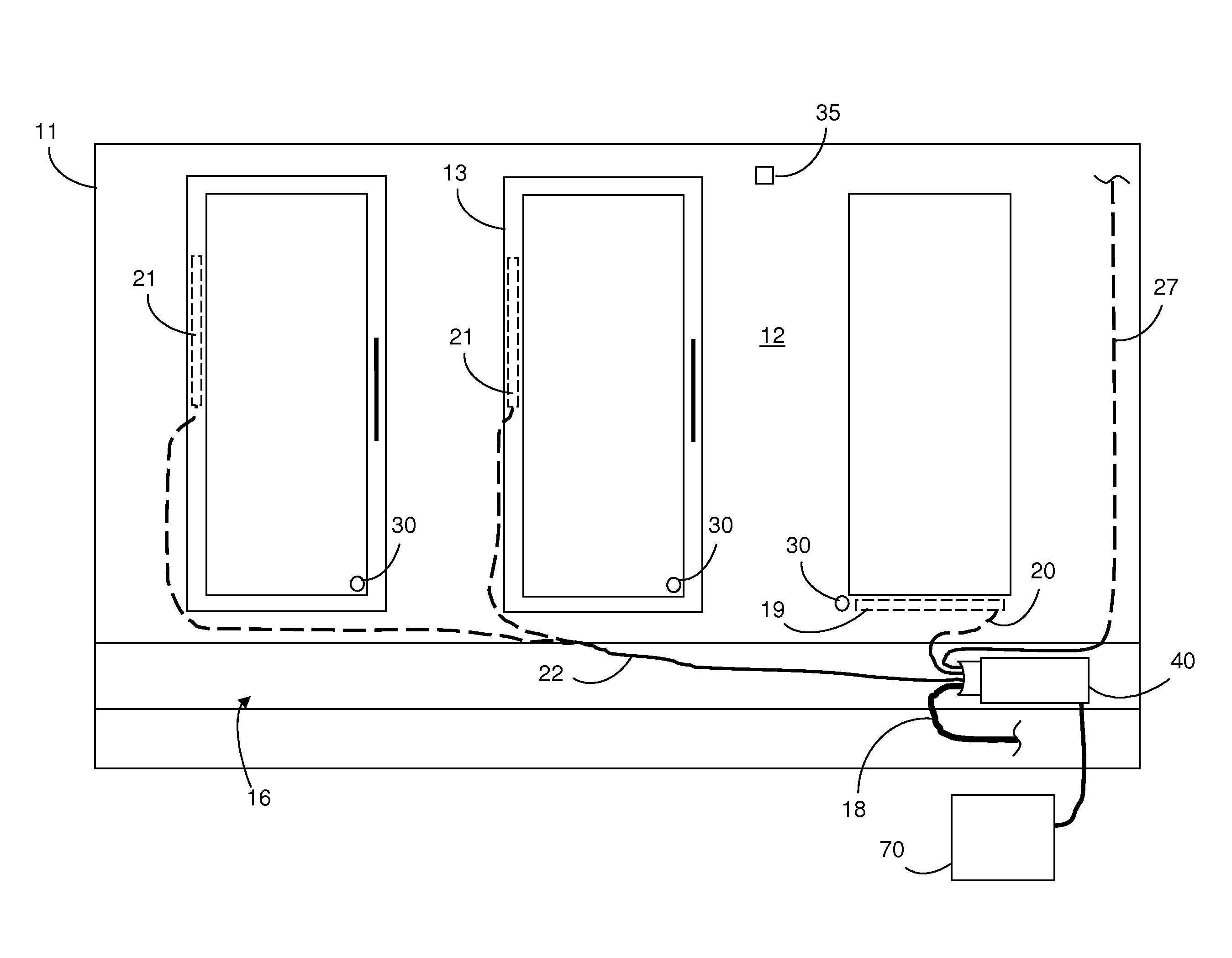
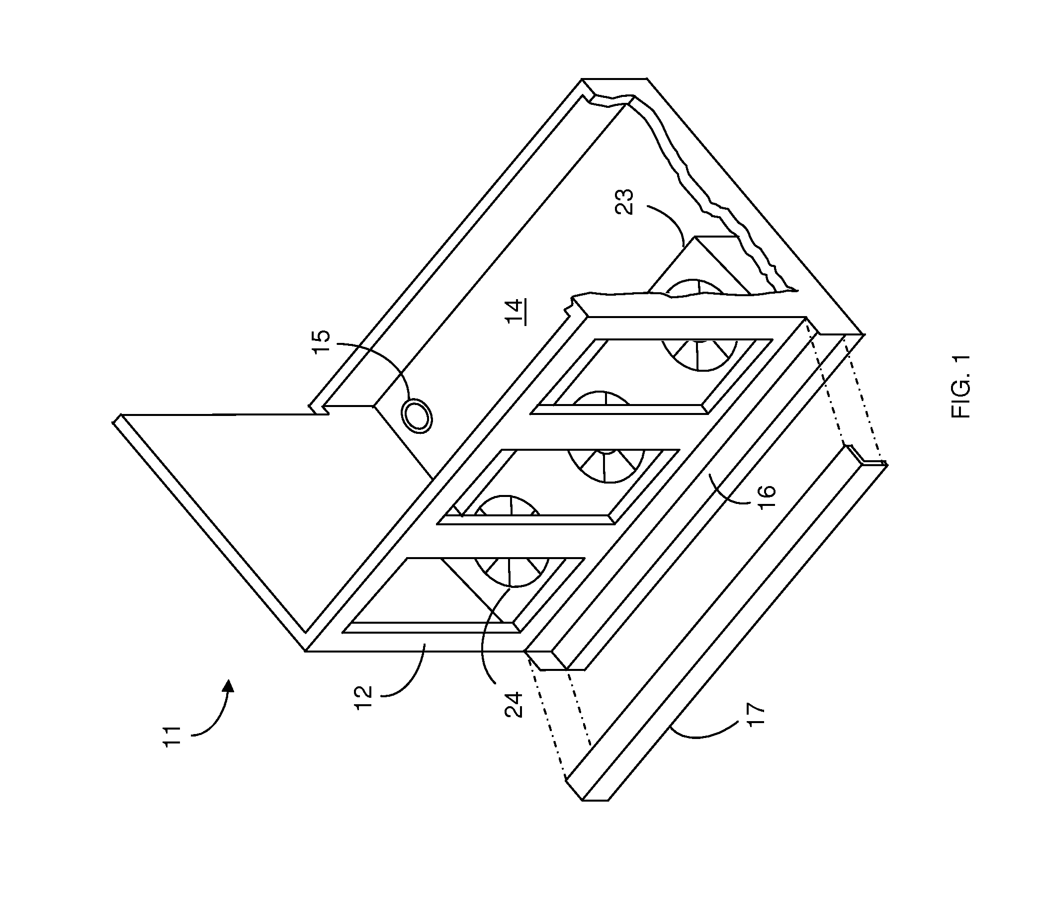
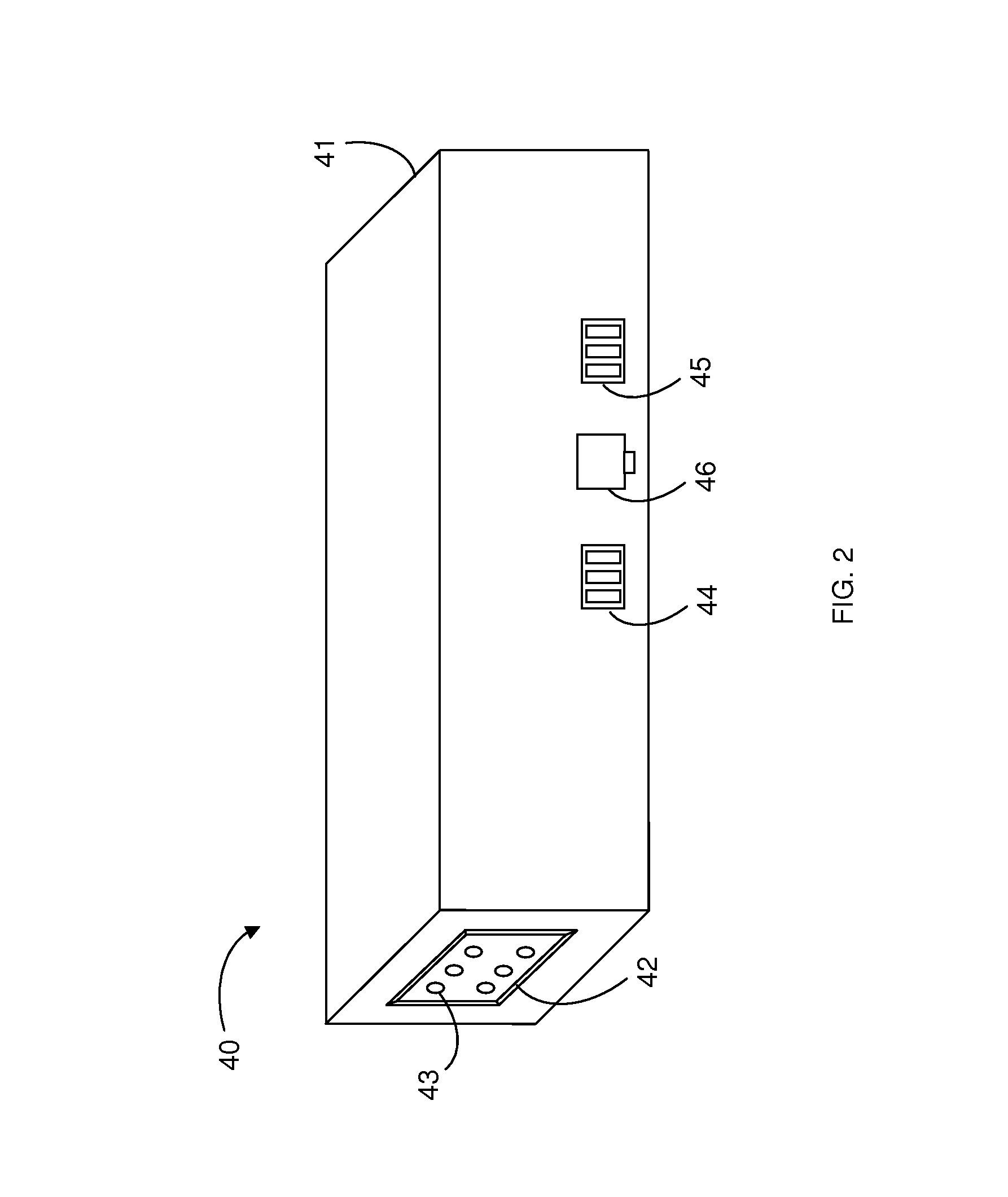
[0021]Referring to FIGS. 1-4, a refrigerator control and monitoring system is used to manage energy consumption and prevent condensation on the doors 13 and frame 12 of a refrigerator 11. The system comprises a control unit 40 that receives input from one or more sensors and uses the input to manage the refrigerator 11. The control unit 40 controls the operation of the refrigerator's 11 frame heaters 19, which contact the frame 12, and door heaters 21, which contact the door's 13 frame or glass, by supplying or denying power to the heaters 19, 21. The control unit 40 may further control the operation of refrigerator 11 fans 24 and lights (not pictured). The control unit 40 may transmit collected sensor data to a central monitoring station, such as a computer 70 or a separate command unit 71 as described below. In the preferred embodiment, the system includes one control unit 40 for each refrigerator 11 in a store or other location. Each control unit 40 is located apart from the heat...


PUM


Abstract

An improved refrigerator energy management system removes condensation from glass refrigerator doors in an energy efficient manner by operating refrigerator frame heaters independently of refrigerator door heaters. Sensors for detecting humidity or condensation transmit data to a control unit that controls electrical current supplied to separate door and frame heater wires. Additional sensors for controlling the refrigerator lighting and monitoring the power consumption of refrigerator fans may transmit data to the control unit. A command unit may receive data from multiple control units, compile the data, and make it available over the internet to a shopkeeper monitoring the system from a remote location. The sensors, control unit, and command unit all communicate on a wireless peer-to-peer network using the ZigBee protocol.

Description

CROSS-REFERENCE TO RELATED APPLICATIONS[0001]This application claims the benefit of and is a continuation-in-part of co-pending application Ser. No. 11 / 228,602, filed Sep. 16, 2005, which is a continuation-in-part of application Ser. No. 10 / 778,289, filed Feb. 11, 2004, now U.S. Pat. No. 7,240,501, both of which are incorporated herein by reference.FIELD OF INVENTION[0002]This invention relates generally to refrigeration devices. This invention relates particularly to a device for managing energy consumption by a refrigerator while maintaining protection against condensation.BACKGROUND[0003]Shopkeepers display refrigerated or frozen products in temperature-controlled display cases, such as refrigerators with glass display doors or open-air, “coffin,” coolers. The refrigerators and freezers are referred to herein as “refrigerators.” Changes in temperature and humidity in the surrounding area cause condensation and frost to build up on the refrigerators. Condensation on doors obstruct...

Claims


Application Information

Patent Timeline
IPC IPC(8): F25D21/06F25D21/00A47F3/04
CPCA47F3/0482F25D21/04Y02B60/50F25D21/02F25B2600/07
Inventor BUNCH, JOHN
Owner SUPERMARKET ENERGY TECH
Why Eureka
Try Eureka