
Acoustic leak detection system and method with enviromental noise isolation

a leak detection system and environmental noise technology, applied in the direction of instruments, structural/machine measurement, material analysis using sonic/ultrasonic/infrasonic waves, etc., can solve the problems of pipeline leakage, poor construction, poor maintenance, etc., and achieve the effect of minimizing external interferen

Inactive Publication Date: 2013-09-24
KING FAHD UNIVERSITY OF PETROLEUM AND MINERALS
View PDF24 Cites 8 Cited by
  • Summary
  • Abstract
  • Description
  • Claims
  • Application Information

AI Technical Summary

Benefits of technology

[0008]The acoustic leak detection system and method with environmental noise isolation provides for the acoustic detection of leaks in a pipe while minimizing interference from external or environmental noise. The acoustic leak detection system includes a hollow shell adapted for positioning about the pipe to be inspected. The hollow shell preferably has first and second portions releasably secured to one another. The first and second portions forming the hollow shell are preferably formed from an acoustically insulating material.

Problems solved by technology

Pipelines suffer from leakage due to excess fluid pressure, corrosion caused by reactions with moving fluid or a surrounding medium, cracks due to aging, poor construction, poor maintenance or the like.
Pipeline leakage may present serious environmental and economic problems.
Typical conventional pipeline leak detection systems are relatively inefficient in terms of response time, sensitivity, robustness and cost.
Neither of these methods provides real-time monitoring of the leak itself, only the indirect effects of a leak.
Typical acoustic detection methods suffer from location in noisy environments, i.e., pipeline networks are often located in or near industrial environments, traffic roads, subways, airports or the like.
In such noisy environments, acoustic noise generated by the leak is often masked by background noise, particularly at the early stage of leakage when the acoustic signal of the leak is weakest.
In such circumstances, the leak signal to noise ratio becomes considerably small.

Method used


Image

  • Acoustic leak detection system and method with enviromental noise isolation
  • Acoustic leak detection system and method with enviromental noise isolation
  • Acoustic leak detection system and method with enviromental noise isolation

Examples


Embodiment Construction

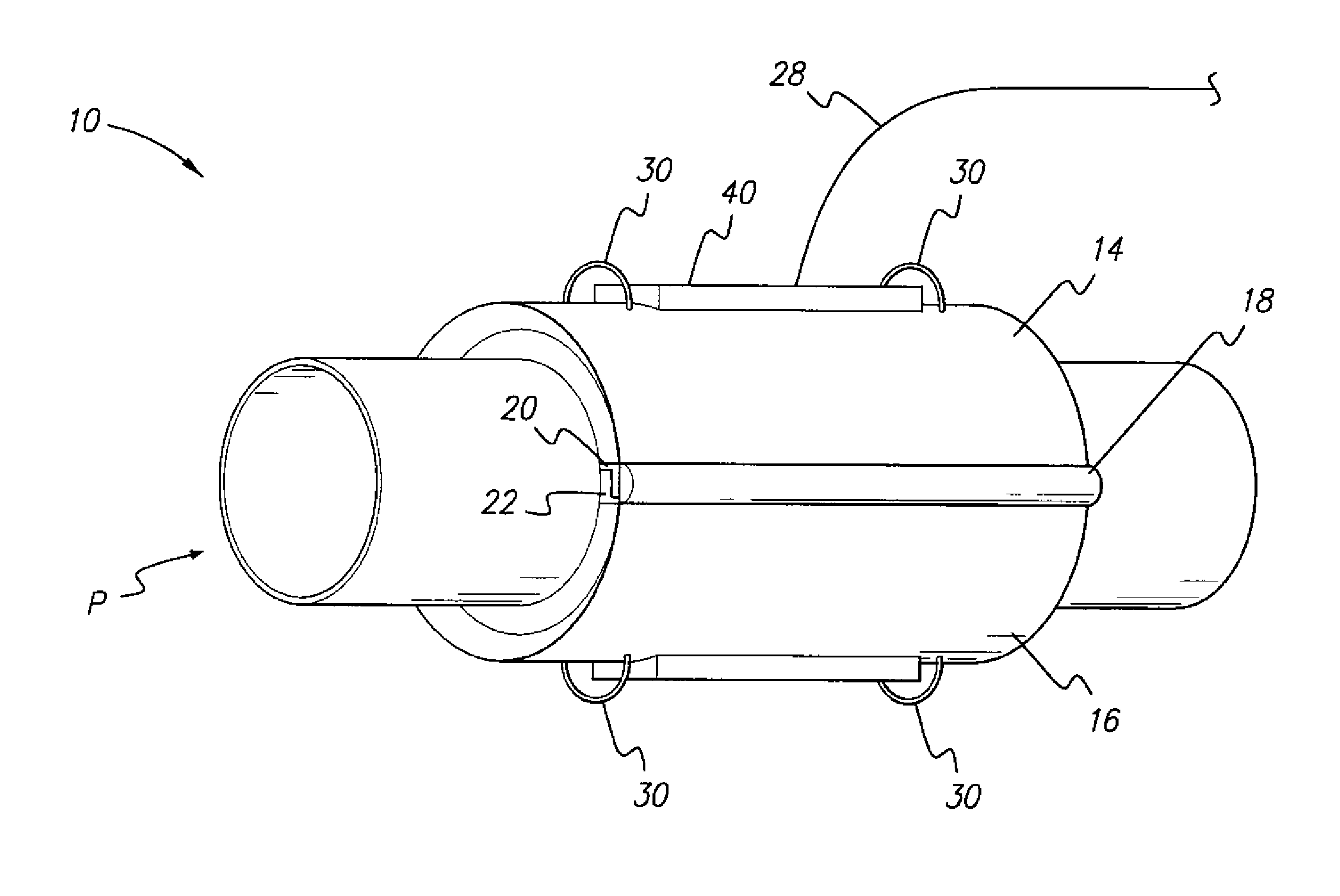
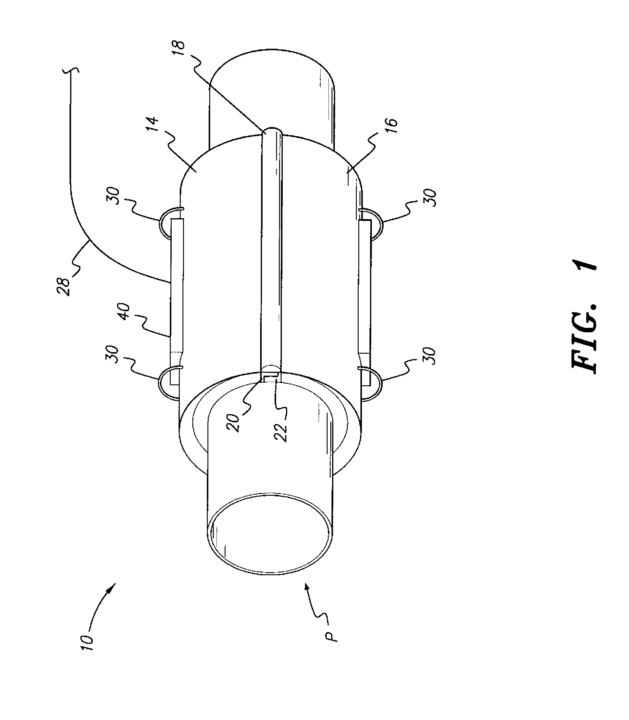
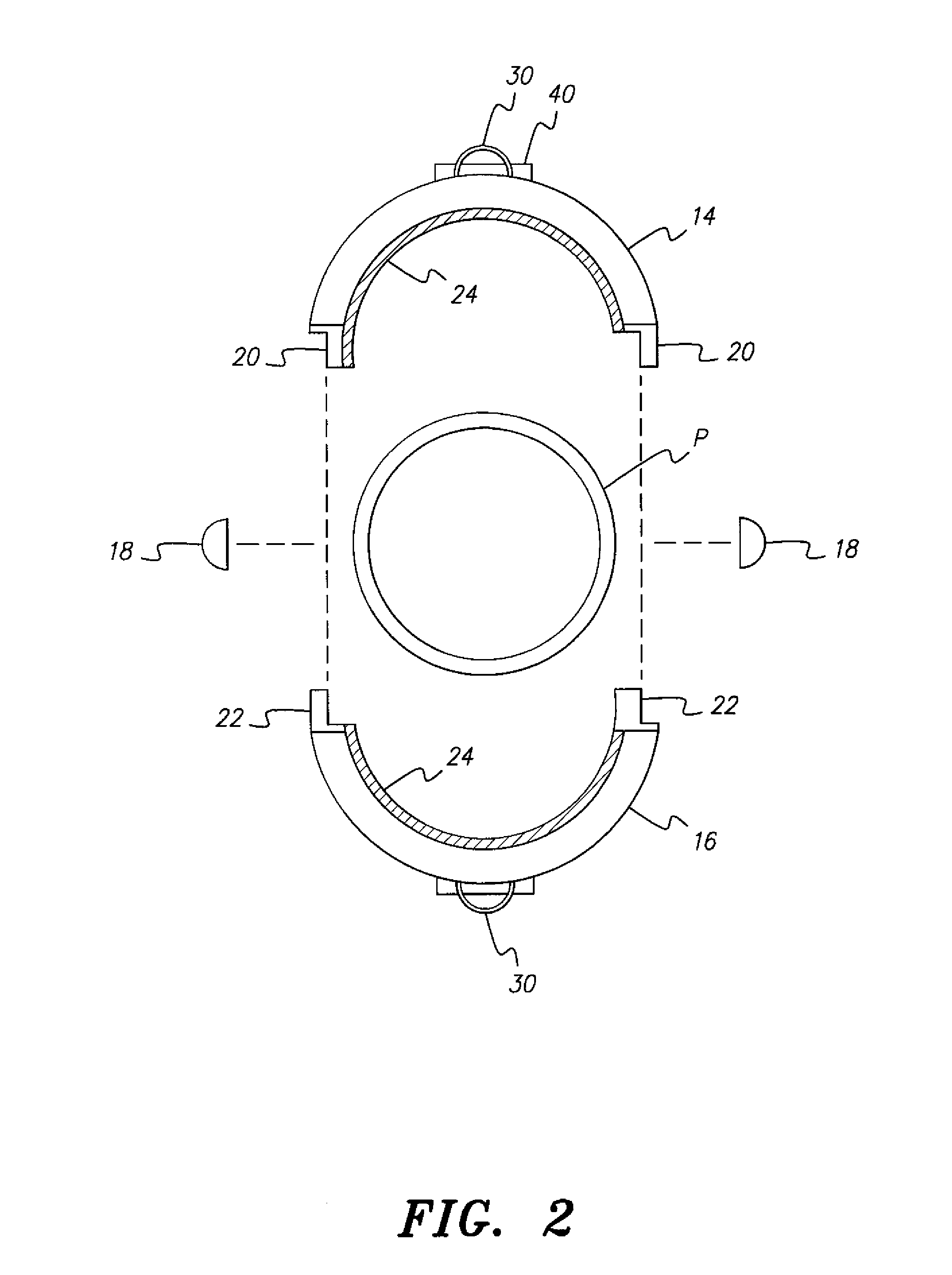
[0017]Referring to FIG. 1, the acoustic leak detection system with environmental noise isolation, designated generally as 10 in the drawings, provides for the acoustic detection of leaks in a pipe P while minimizing interference from external or environmental noise that might otherwise interfere with detection of the leak. As best shown in FIGS. 1 and 2, the acoustic leak detection system 10 includes a hollow shell adapted for positioning about the pipe P to be inspected. The hollow shell preferably has first and second portions 14, 16, respectively, which are releasably secured or attached to one another. The first and second portions 14, 16 forming the hollow shell are preferably formed from an acoustically insulating material.

[0018]In FIGS. 1 and 2, the hollow shell is shown as being substantially cylindrical, the first and second portions 14, 16 each being substantially semicylindrical. It should be understood that the hollow shell may be any shape that can be fastened around th...


PUM


Abstract

The acoustic leak detection system with environmental noise isolation provides for the acoustic detection of leaks in a pipe while minimizing interference from external or environmental noise. The acoustic leak detection system includes a hollow shell adapted for positioning about the pipe to be inspected. A pair of gaskets are circumferentially secured to the inner surface of the hollow shell so that the pair of gaskets bear against the outer surface of the pipe to form an acoustically isolated region defined between the pipe, the pair of gaskets and the inner surface of the hollow shell. An acoustic sensor, microphone or the like is mounted on the hollow shell within the acoustically isolated region for detecting any acoustic signals; i.e., the sound produced by a leak in the pipe within the acoustically isolated region. Upon detection of a leak, an alert signal is generated.

Description

BACKGROUND OF THE INVENTION[0001]1. Field of the Invention[0002]The present invention relates generally to pipes for transporting fluids, such as water, gas, chemical fluid and the like, and particularly to an acoustic leak detection system and method with environmental noise isolation, applicable to pipes and couplings, that generates an alert signal when a liquid leak from a pipe joint or coupling is detected.[0003]2. Description of the Related Art[0004]Pipelines suffer from leakage due to excess fluid pressure, corrosion caused by reactions with moving fluid or a surrounding medium, cracks due to aging, poor construction, poor maintenance or the like. Pipeline leakage may present serious environmental and economic problems. Thus, leaks should be quickly detected, located and repaired.[0005]Typical conventional pipeline leak detection systems are relatively inefficient in terms of response time, sensitivity, robustness and cost. Pipeline leaks are typically detected by observation...

Claims


Application Information

Patent Timeline
Patent Type & Authority Patents(United States)
IPC IPC(8): G01M3/18
CPCG01M3/243
Inventor AL-QAHTANI, HUSSAIN M.HAWWA, MUHAMMAD A.
Owner KING FAHD UNIVERSITY OF PETROLEUM AND MINERALS
Learn More