Detachable self-expanding aneurysm cover device

a self-expanding, aneurysm technology, applied in the field of repositionable self-expanding intravascular aneurysm cover devices, can solve the problems of difficult, if not impossible, to retrieve the stent or reposition the stent, and achieve the effect of reducing the outside diameter, easy removal from the vessel, and increasing the lumen siz

Active Publication Date: 2013-09-24
DEPUY SYNTHES PROD INC
View PDF37 Cites 20 Cited by
  • Summary
  • Abstract
  • Description
  • Claims
  • Application Information

AI Technical Summary

Benefits of technology

[0014]In accordance with one aspect of the present invention, the self-expanding aneurysm cover device deployment system also includes a delivery catheter through with the device is delivered to the predetermined location. Initially, the device is retained by the deployment catheter within a delivery catheter and the device is positioned within the lumen of the distal section of the delivery catheter. The deployment catheter and the delivery catheter are moved to a desired position within a vessel and the deployment catheter is moved distally to permit the device to be pushed out of the distal end of the delivery catheter. The aneurysm cover device, being a self-expanding device, expands radially and contacts the walls of the vessel. If, prior to the final release of the aneurysm cover device from the deployment catheter it is determined that the device should be repositioned to another position within the vessel, the deployment catheter may be moved proximally back into the delivery catheter. As the aneurysm cover device is withdrawn into the delivery catheter, the device collapses to fit within the lumen of the delivery catheter. Once the device has been withdrawn into the delivery catheter, the delivery catheter may be moved into another position within the vessel for repositioning and subsequent release of the device. Accordingly, with this aneurysm cover device design is possible to permit the self-expanding device to completely expand at a first location, to then withdraw the device back into the delivery catheter, to move the delivery catheter to a second position and to again expand the device at the second position for subsequent release of the device.
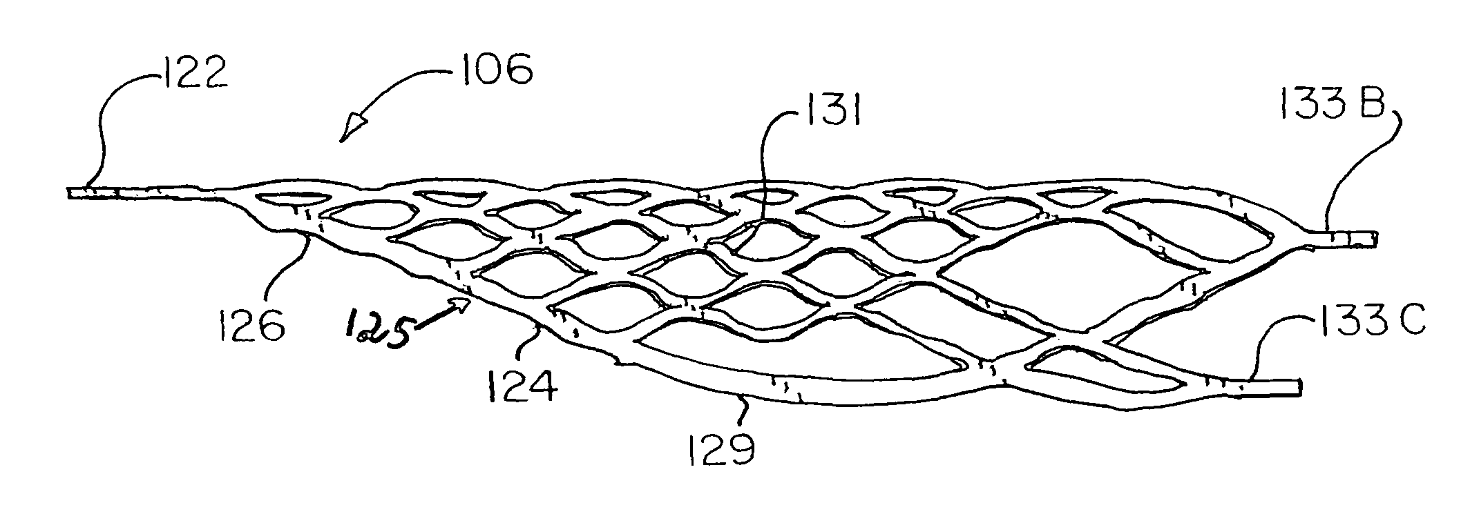
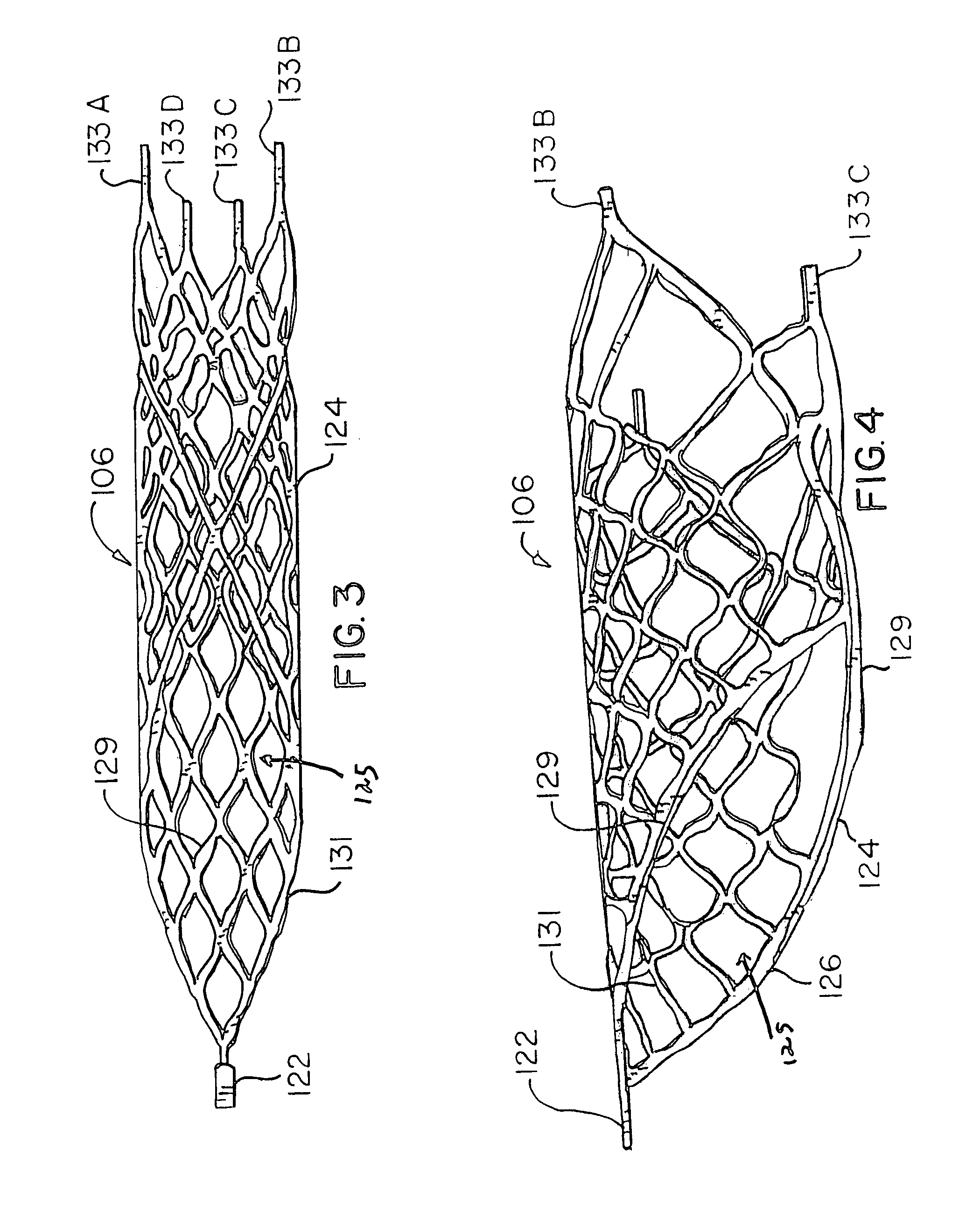
[0015]In accordance with another aspect of the present invention, the self-expanding aneurysm cover device includes a generally cylindrical skeletal frame in which the frame includes a proximal loop portion, a positioning tab attached to the proximal loop portion and extending from the loop portion in a direction generally parallel to the longitudinal axis of the skeletal frame, and also includes a distal spring biased portion connected to the loop portion along at least two spaced apart locations on the loop portion. The skeletal frame is adapted to assume a first expanded position in which the spring portion is expanded to thereby cause the loop portion to be expanded to form a generally cylindrical loop configuration which lies in a plane extending in an oblique angle to the longitudinal axis of the skeletal frame. When the tab is moved proximally, the skeletal frame becomes compressed so that the loop portion lies in a plane extending closer to parallel to the longitudinal axis of the skeletal frame thereby causing the spring-biased portion to collapse which in turn causes the loop portion to collapse for easy withdrawal of the aneurysm cover device from a vessel.
[0017]In accordance with still another aspect of the present invention, the aneurysm cover device includes a generally cylindrical frame having a first condition in which said cylindrical skeletal frame may be compressed to have an overall small outside diameter and a normally biased second condition in which the cylindrical skeletal frame has an overall larger diameter. The cylindrical skeletal frame defines a loop portion at its proximal end in which the loop portion lies in a plane extending at an oblique angle to the longitudinal axis of the cylindrical skeletal frame. Also the device includes a positioning tab attached to the loop portion and extending from the proximal end of the loop portion in a direction generally parallel to the longitudinal axis of the skeletal frame. When a pulling force is applied to the positioning tab in a direction proximal to the cylindrical frame, the cylindrical frame is caused to collapse to form a device which has a reduced outside diameter therefore which may be easily removed from a vessel.

Problems solved by technology

With these placements systems there is very little control over the exact placement of the stent since the stent may be ejected to a position some distance beyond the end of the cannula.
As is apparent, with these latter systems, when the stent has been released from the cannula it is difficult, if not impossible, to retrieve the stent or to reposition the stent.

Method used


Image

  • Detachable self-expanding aneurysm cover device
  • Detachable self-expanding aneurysm cover device
  • Detachable self-expanding aneurysm cover device

Examples


Embodiment Construction

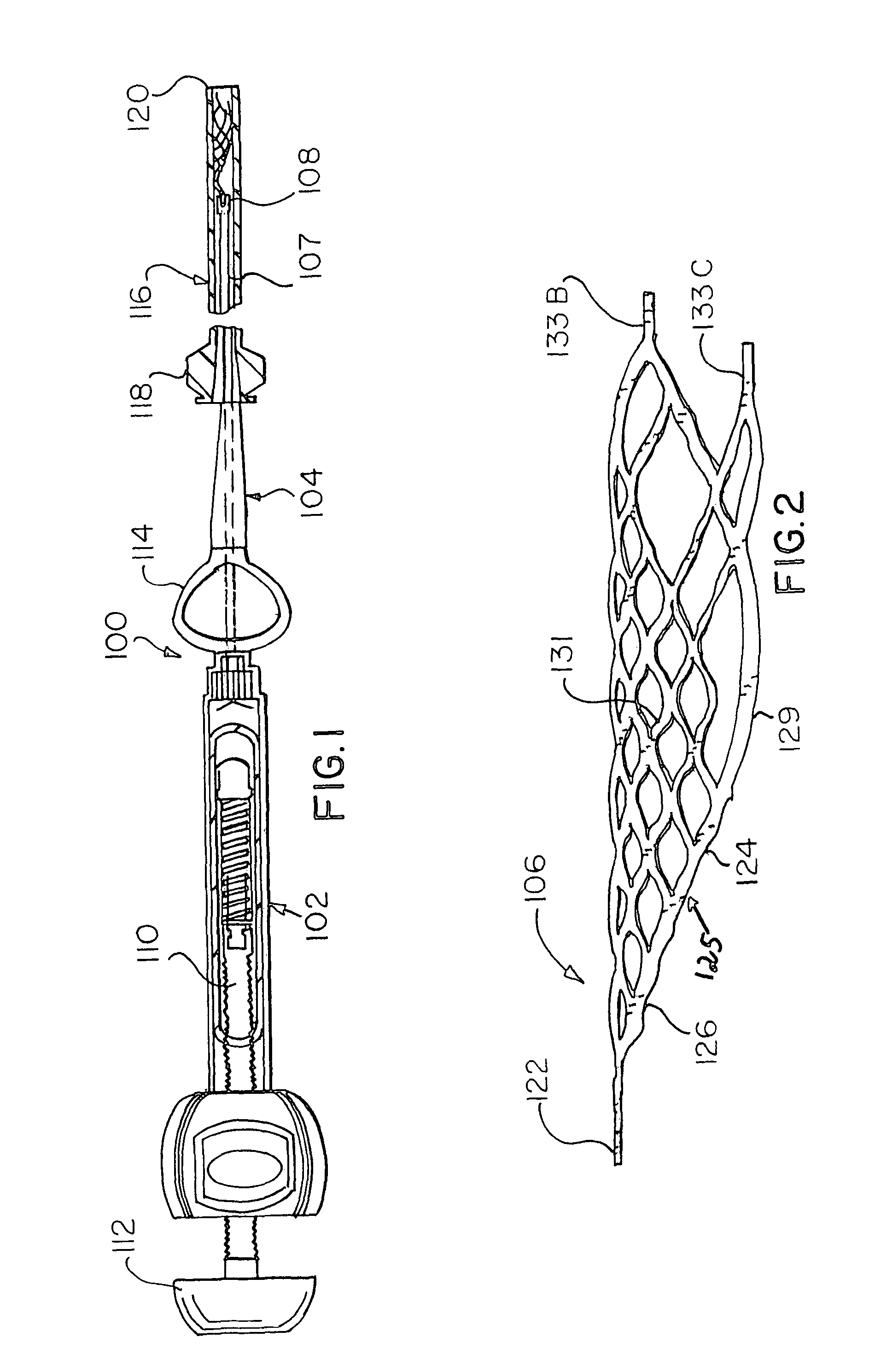
[0026]FIG. 1 generally illustrates the intravascular aneurysm cover device deployment system 100 which is comprised of a hydraulic injector or syringe 102, coupled to the proximal end of a deployment catheter 104. An intravascular aneurysm cover device is disposed within the lumen of the distal section 108 of the catheter 104. The proximal end of the aneurysm cover device is tightly held within the lumen of the distal section 108 of the catheter 104 until the deployment system is activated for release of the aneurysm cover device. As may be seen, the syringe 102 includes a threaded piston 110 which is controlled by a handle 112 for infusing fluid into the interior of the catheter 104. Also as illustrated, the catheter 104 includes a winged hub 114 which aids in the insertion of the catheter into the access catheter 116 which has a proximal hub 118 that is placed in the vascular system of the body. The intravascular aneurysm cover device deployment system 100 is described in more det...


PUM


Abstract

A self-expanding aneurysm cover device which takes the form of an outwardly biased cylindrical skeletal frame in which the proximal end of the cylindrical skeletal frame forms a loop which extends at an oblique angle to the axis of the cylindrical skeletal frame. A positioning tab extends from the proximal end of the skeletal frame which when pulled causes the cylindrical skeletal frame to collapse to a reduced diameter for removal of the device from a vessel.

Description

CROSS-REFERENCE TO RELATED APPLICATION[0001]The present application is a continuation-in-part of Ser. No. 10 / 465,975, entitled “Detachable Self-Expanding Aneurysm Cover Device”, filed Jun. 27, 2003 now abandoned.BACKGROUND OF THE INVENTION[0002]1. Field of the Invention[0003]The present invention relates to a repositionable self-expanding intravascular aneurysm cover device and a hydraulic deployment system for placing the device at a preselected location within a vessel of the human body, and more particularly, relates to a device and hydraulic deployment system for the device which may be used to initially place the aneurysm cover device at a first location within a vessel and if it is desirable to reposition the device, the device may be withdrawn into the deployment system and subsequently repositioned at a different location.[0004]2. Description of the Prior Art[0005]For many years flexible catheters have been used to place various devices within the vessels of the human body. ...

Claims


Application Information

Patent Timeline
Patent Type & Authority Patents(United States)
IPC IPC(8): A61F2/06A61B17/12A61F2/82
CPCA61B17/12022A61B17/12118A61B2017/1205A61F2230/0008A61F2/95A61F2002/823A61F2/91
Inventor JONES, DONALD K.MITELBERG, VLADIMIR
Owner DEPUY SYNTHES PROD INC
Why Eureka
Try Eureka