
Linear motion guide unit with retainer for rolling element

a technology of motion guide unit and retainer, which is applied in the direction of bearings, shafts and bearings, bearings, etc., can solve the problems of linear guide unit less mechanical strength, linear guide unit itself is bulky, and prior retainer as recited earlier is not suited to shrink linear guide units in construction, etc., to achieve the desired shape with accuracy, high precision, and high rigidity

Inactive Publication Date: 2008-10-14
NIPPON THOMPSON
View PDF6 Cites 10 Cited by
  • Summary
  • Abstract
  • Description
  • Claims
  • Application Information

AI Technical Summary

Benefits of technology

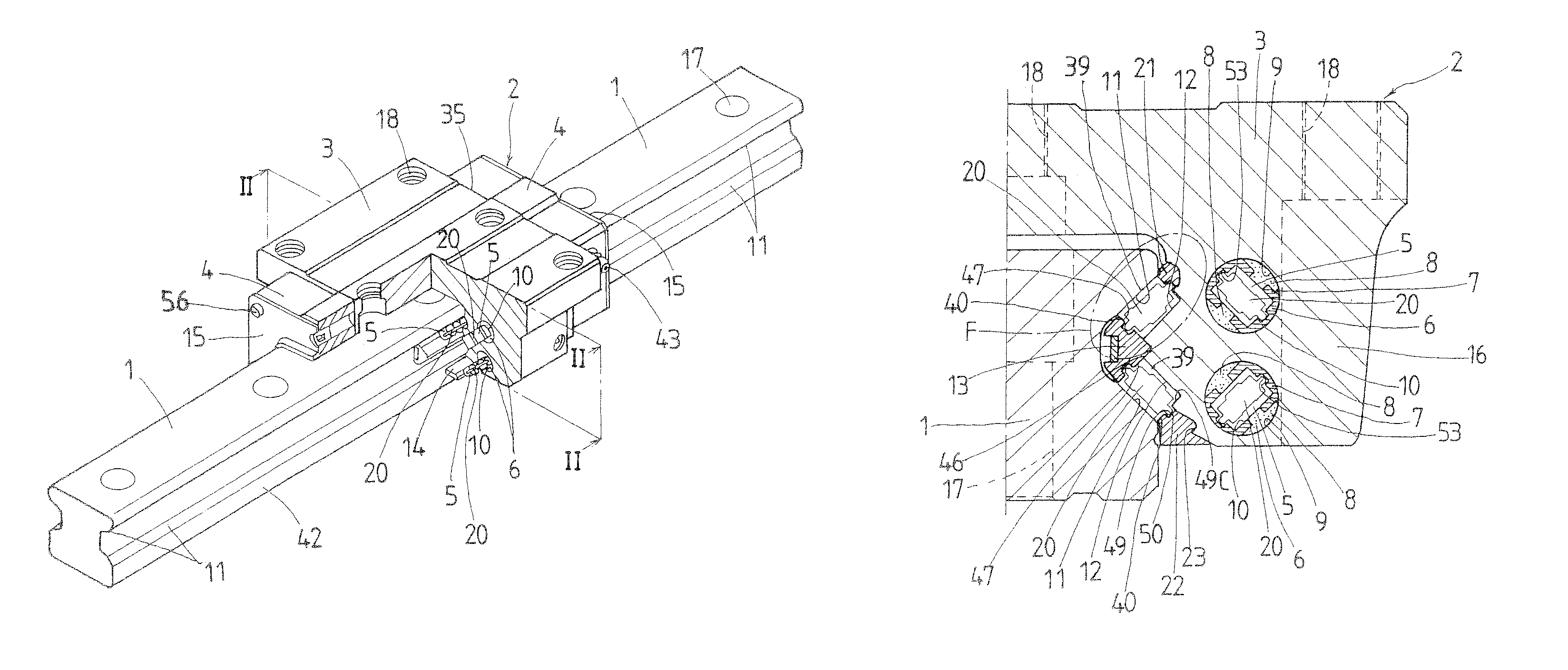
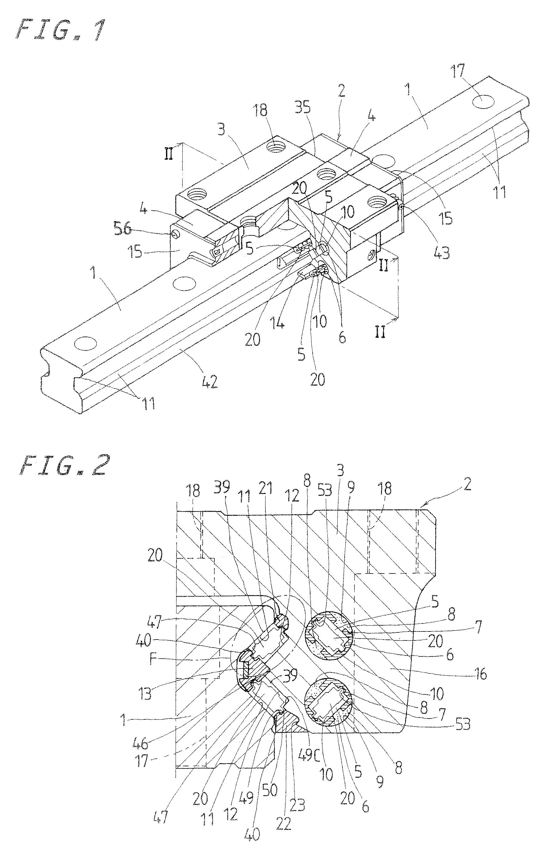
[0017]The present invention has for its primary object to meet the four requisites as recited earlier, and to provide a linear motion guide unit having a retainer therein, the retainer having a lip to keep a roller in place, which is made not to experience any distortion and / or damage when a core is withdrawn from the retainer after molding operation, the lip also serving a variety of functions including coming into certain engagement with a rolling surface around the roller to retain the roller in place with steadiness, sustaining ample lubricant there, and rendering a mold cavity simple in construction, thereby making it easier to mold or cast the retainer with accuracy. The present invention also provides a linear motion guide unit having a retainer, in which the roller is allowed to roll with smoothness and high operating speed, but without exerting any unsuited stress on the retainer. Moreover, the present invention provides a linear motion guide unit having a retainer therein, in which the retainer is kept with a retainer plate in a slider so as to ensure a load-carrying race as long as allowed, and the retainer is formed to retain the rollers as many as possible.
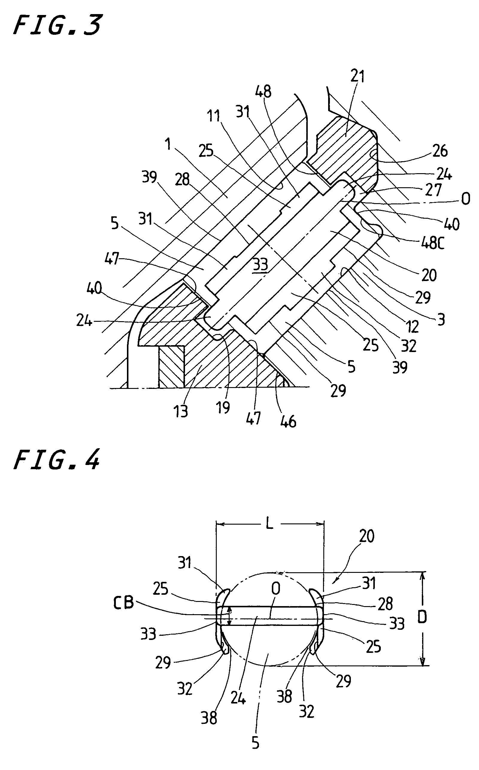
[0036]With the linear motion guide unit with the retainer constructed as stated earlier, the first and second lips made staggered with each other lengthwise of the embracing parts come into engagement with the roller in a way the first lip bears any one side of the roller while the second lip bears another side of the roller, thereby making certain of steady bearing of the roller on either sides thereof. Even upon production of the retainer with using the mold where at least two mold sections or mold halves are retracted in opposite directions to remove the molded retainer out of the mold cavity, especially, the first and second lips staggered with one another on the embracing parts are allowed to escape any interference with the mold opened away from the embracing parts, which might otherwise cause any damage or undesirable stress on the first and second lips owing to the unsuited force raised from the withdrawal of the mold sections. Thus, the first and second lips of the present invention are ensured to have their desired shape with accuracy. Moreover, anywhere other than the first and second lips on the embracing parts has the functions of the relief for easy withdrawal of the mold sections to open the mold cavity for removal of the molded retainer out of the mold cavity as well as the lubricant reservoir that can apply ample lubricant to the load-carrying race so as not to cause no lubrication failure. Thus, the linear motion guide unit of the present invention may be expected to better live up to various operating performances including high precision, high stiffness, high sliding velocity, high acceleration / deceleration, less noise, and so on.

Problems solved by technology

Nevertheless, the retainer constructed as stated just earlier, as being made to cover the overall axial length of the roller, unfortunately needs the circulating circuit larger in diametral dimension of a passage caliber, making the linear guide unit itself bulky.
This means that the prior retainer as recited earlier is not suited to shrink the linear guide unit in construction.
The retainer of the type in which the roller fits with molding, moreover, is not ready for modern operating needs for high traveling speed, high acceleration / deceleration, and so on because a clearance left between the retainer and the roller is so tiny to trend to cause lubrication failure.
This results in making the linear guide unit less in mechanical strength.
This means that the prior retainer as recited earlier also is not suited to shrink the linear guide unit in construction.
The retainer made at the leading edge thereof with the raised portion while cut away partially is intricate in construction, which would need too sophisticated mold cavity in the injection molding process to prepare for the roller very small in diameter.
The retainer of the type in which the roller fits with molding, moreover, is not ready for modern operating needs for high traveling speed, high acceleration / deceleration, and so on because a clearance left between the retainer and the roller is so tiny to trend to cause the issue of lubrication failure.
However, the linear motion guide unit constructed as stated just above also is not suited to shrink the linear guide unit in construction, because the retainer has the guide portions bent into U-shape that would need to make the grooves in the circulating circuit much larger.
The retainer itself is extremely intricate in construction, which would need very sophisticated mold cavity in the injection molding process.
In addition, the prior retainer recited just above, since made stiff or rigid in construction, is unsuited for smooth traveling to negotiate easily the turnaround passage curved sharply.
This necessity of the additional core would often create a collateral problem of raising intricacy of assembled molds to withdraw successfully the cores without any interference with their associated spacers.
This forced extraction of the cores could likely cause either any permanent distortion or any damage in the chain or ladder.
Forced extraction of the cores, moreover, would raise the issue negatively affecting the service life of the chain or ladder.
Furthermore, the chain retainer, although made of synthetic resin rich in flexibility, is ready to swell with water, oil, and so on, thereby more likely to shear off.

Method used


Image

  • Linear motion guide unit with retainer for rolling element
  • Linear motion guide unit with retainer for rolling element
  • Linear motion guide unit with retainer for rolling element

Examples


Embodiment Construction

[0054]The linear motion guide unit according to the present invention is adapted for use in any relatively sliding components in machinery as diverse as semiconductor processing machines, various assembling machines, precision machines, measurement / inspection instruments, medical instruments, micromachines, machine tools, and so on.

[0055]Referring now in detail to the drawings, the linear motion guide unit according to the present invention will be explained below. The linear motion guide unit of the present invention features that there is provided therein a retainer 20 used to space adjacent cylindrical rollers 5 for rolling element from each other to keep constantly the rollers 5 against direct engagement with one another, thereby making sure of various operating performances including high precision, high stiffness, high sliding velocity, high acceleration / deceleration, less noise, and so on. The retainer 20 adopted in the linear motion guide unit of the present invention, altho...


PUM


Abstract

A retainer to be installed in a linear motion guide unit is disclosed which composed of embracing parts to hold a roller on diametrically opposite sides thereof, and connecting flanges joining the embracing parts together with one another. The embracing parts to hold the roller between them are each made with a first lip raised above any one side thereof, and a second lip raised above another side thereof. The first and second lips raised in opposite direction are placed in an offset or staggered relation with one another in lengthwise direction of the embracing part or in axial direction of the roller so as to be tough to suffer any distortion and / or damage on molding operation. The retainer can sustain ample lubricant near the lips. The embracing parts come into rolling-contact with the rolling surface of the roller while the connecting flanges come into sliding contact with axially opposite ends of the roller.

Description

FIELD OF THE INVENTION[0001]The present invention relates to a linear motion guide unit with retainers, sometimes called separators to space rolling elements from each other, which is comprised of an elongated guide rail, and a slider that is allowed to move on the elongated guide rail relatively to the guide rail by virtue of more than one rolling element of roller.BACKGROUND OF THE INVENTION[0002]Modern advanced technology extensively requires various sorts of linear motion guide units, especially, linear motion guide units of the type using rolling elements of cylindrical roller, which are also required to live up to various operating performances including high precision, high stiffness, high sliding velocity, high acceleration / deceleration, less noise, and so on. To cope with this, there have been conventionally provided linear motion guide units in which separators are interposed between any two adjoining rolling elements.[0003]In Japanese Utility Model Laid-Open No. S63-69816...

Claims


Application Information

Patent Timeline
Patent Type & Authority Patents(United States)
IPC IPC(8): F16C29/06
CPCF16C29/0607F16C29/065F16C33/467F16C33/51
Inventor KUWABARA, HIDEKI
Owner NIPPON THOMPSON
Learn More