Device connector and method of manufacture

a technology of device connectors and manufacturing methods, which is applied in the direction of coupling device connections, other domestic articles, coatings, etc., can solve the problems of voids (small clearances), voids that cannot be produced, and the lateral length of cores in the primary molded portion can be reduced, and the formation of voids in the primary molded portion can be suppressed

Inactive Publication Date: 2013-10-01
SUMITOMO WIRING SYST LTD
View PDF76 Cites 61 Cited by
  • Summary
  • Abstract
  • Description
  • Claims
  • Application Information

AI Technical Summary

Benefits of technology

[0012]The nut accommodating portion conforms with the width of the nut and the escaping recess conforms with the outer diameter of a shaft of the fastening bolt. Thus, the escaping recess is narrower than the nut accommodating portion in the lateral direction. Facing surfaces of the escaping recess include the tight holding portions. Thus, as compared with the case where two facing surfaces of the nut accommodating portion include the tight holding portions, the slide die can be held by the tight holding portions of the primary molded portion without increasing the width of the primary molded portion in the lateral direction. Thus, the primary molded portion is not thickened and voids in the primary molded portion are suppressed.
[0014]The escaping recess may include a bottom wall that connects the tight holding portions. The slide die may be held tightly from upper and lower sides by the fastening portion of the conductor and the bottom wall. Thus, the primary molded article tightly holds the slide die with respect to the vertical direction to prevent vertical displacements of the primary molded portion.
[0015]The primary molded article may include individually formed cores for the respective conductors. The cores preferably arranged substantially side by side in a lateral direction. Thus, the lengths of the cores in the lateral direction in the primary molded portion can be reduced further and the formation of voids in the primary molded portion can be suppressed further.

Problems solved by technology

Accordingly, a demolding structure for the molded resin portion becomes complicated and suitable boring cannot be performed on the molded resin portion.
Thus, voids (small clearances) may be produced in a thick part of the molded resin.
The voids may lead to cracks that reduce the waterproof property of the device connector.
However, injection pressure of the molding resin may cause the primary molded article to incline in the secondary molding die.
Thus, the secondary molded portion cannot be formed with the busbars at proper positions.

Method used


Image

  • Device connector and method of manufacture
  • Device connector and method of manufacture
  • Device connector and method of manufacture

Examples


Embodiment Construction

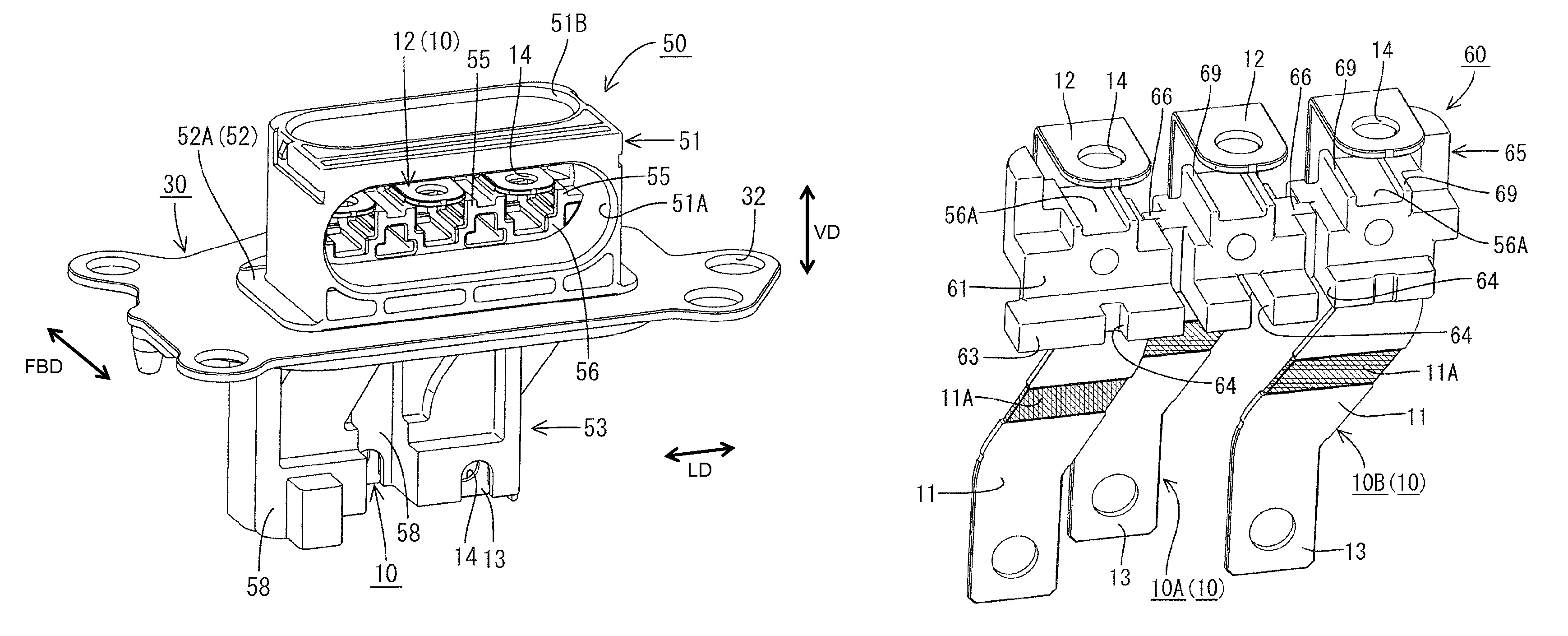
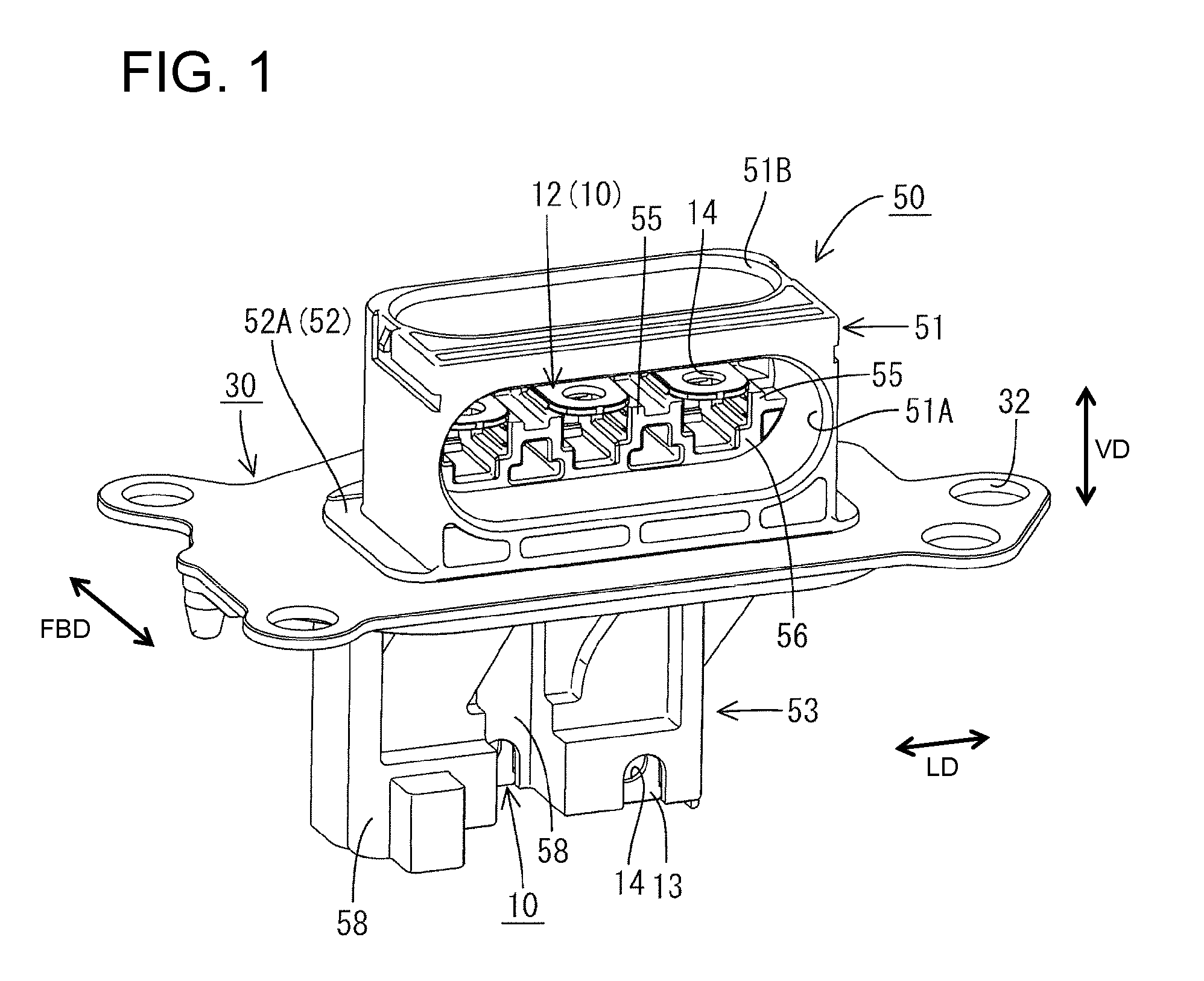
[0029]A device connector in accordance with the invention is a terminal block that is to be attached to a metal motor case (not shown) that houses a motor, or other such device. As shown in FIG. 1, the terminal block includes a metal plate 30 to be attached and fixed to the motor case, a molded resin housing 50 molded to be integral to the metal plate 30, and three conductive plates 10 held in the housing 50 while penetrating through the metal plate 30 in a plate thickness direction TD.

[0030]First ends of the conductive plates 10 are to be bolt-fastened to unillustrated device-side busbars at the motor case for electrical connection. On the other hand, in an inverter or other such power supply device for supplying power such as an inverter, wires are arranged to extend toward the motor case and an unillustrated wire-side connector is provided at ends of the wires. Wire-side terminals connected to respective wire ends are provided in the wire-side connector and are bolt-fastened to t...


PUM

PropertyMeasurementUnit
shapesaaaaaaaaaa
thickaaaaaaaaaa
waterproof propertyaaaaaaaaaa

Abstract

A terminal block in which a plurality of metal conductive plates (10) to be connected to device-side busbars provided in a motor are made integral by a connector housing (50) includes a primary molded article (60) in which the plurality of conductive plates (10) are made integral by a connector housing (50); a metal plate (30) to be attached and fixed to a motor case; and a secondary molded portion (70) integrally forming the primary molded article (60) and the metal plate (30). The secondary molded portion (70) is formed by a secondary molding die including both upper and lower dies (90, 91) and a slide die (92). Pairs of tight holding portions (69, 69) for tightly holding the slide die (92) are provided on the primary molded portion (61) before the secondary molded portion (70) is formed.

Description

BACKGROUND OF THE INVENTION[0001]1. Field of the Invention[0002]The invention relates to a device connector and a method of manufacturing a device connector.[0003]2. Description of the Related Art[0004]U.S. Pat. No. 7,572,150 discloses a device connector to be connected to a device, such as a motor, installed in an electric vehicle or a hybrid vehicle. This device connector includes metal busbars for connecting device-side terminals in the device to wire-side terminals on power feeding wires. A molded resin portion covers the busbars. More particularly, insert molding is performed with the busbars bent into complicated shapes and arranged side by side. Accordingly, a demolding structure for the molded resin portion becomes complicated and suitable boring cannot be performed on the molded resin portion. Thus, voids (small clearances) may be produced in a thick part of the molded resin. The voids may lead to cracks that reduce the waterproof property of the device connector.[0005]Stud...

Claims


Application Information

Patent Timeline
Patent Type & Authority Patents(United States)
IPC IPC(8): H01R13/58
CPCB29C45/14B29C45/14467B29C45/14639H01R43/24H01R13/504H01R43/18B29C45/33B29L2031/36
Inventor SAKAMOTO, SHINICHITATE, TAKUYA
Owner SUMITOMO WIRING SYST LTD
Why Eureka
Try Eureka