Golf club

a golf club and surface integrity technology, applied in the field of golf clubs, can solve the problems of shortening the service life poor surface integrity of the golf club, and higher cost of components, and achieve the effect of improving surface integrity

Active Publication Date: 2013-10-01
FUSHENG PRECISION
View PDF5 Cites 6 Cited by
  • Summary
  • Abstract
  • Description
  • Claims
  • Application Information

AI Technical Summary

Benefits of technology

[0010]It is therefore the primary objective of this invention to provide a golf club with better surface integrity.
[0011]It is another objective of this invention to provide a golf club that prevents moisture in the air from entering a head thereof, thereby keeping the components inside the head from becoming oxidized or rusted.

Problems solved by technology

However, since the golf club requires drilling the head 81 to form the bolt hole 813, the surface integrity of the golf club will be poor.
This may lead to component loosening and may shorten the service life of the golf club.
Moreover, because the golf club is assembled by many components, component costs are higher, and a complex assembly procedure results.
This also affects the surface integrity of the golf club and causes moisture in the air to enter the head 91.
As a result, the components inside the head 91 may still become oxidized or loosened, shortening the service life of the golf club.

Method used


Image

  • Golf club
  • Golf club
  • Golf club

Examples


first embodiment

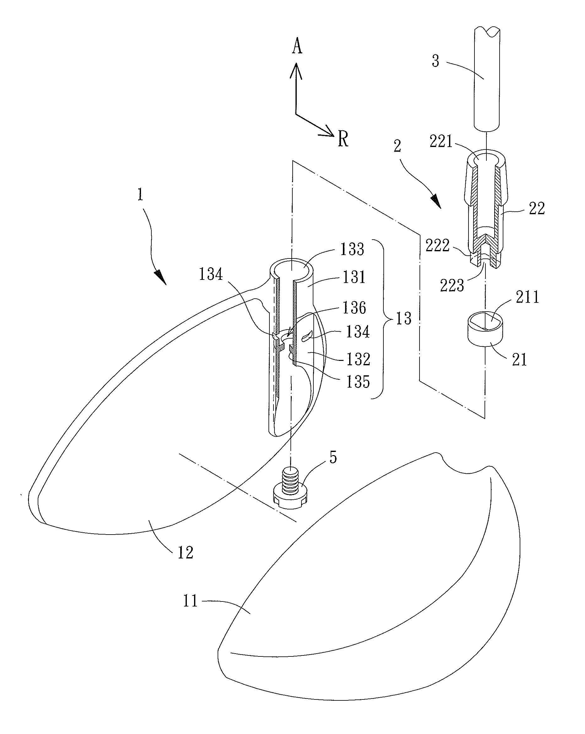
[0022]Referring to FIGS. 3 and 4, a golf club comprising a head 1, a removable assembly 2 and a shaft 3 is disclosed according to the invention. The head 1 is coupled with one end of the shaft 3 via the removable assembly 2. A user can hold the shaft 3 with hands and hit a ball with the head 1.

[0023]The head 1 comprises a body 11, a striking panel 12 and a sleeve 13. The body 11 is coupled with the striking panel 12. The sleeve 13 can be sandwiched between the body 11 and the striking panel 12. Alternatively, the sleeve 13 can also be integrally formed on the body 11 or the striking panel 12. In this embodiment, the sleeve 13 is integrally formed on the striking panel 12. The sleeve 13 comprises a neck 131 and an assembling portion 132. The neck 131 protrudes from the body 11 and the striking panel 12. The assembling portion 132 is arranged between and enclosed by the body 11 and the striking panel 12. The neck 131 has an assembling hole 133 extending from one end of the neck 131 to...

second embodiment

[0031]Referring to FIGS. 6 and 7, a golf club comprising a head 1, a removable assembly 6 and a shaft 3′ is disclosed according to the invention. The head 1 has been described in the previous embodiment, so it is not described herein again for brevity.

[0032]The removable assembly 6 has a retaining ring 61, a case 62 and a tightening member 63. The retaining ring 61 also has an insetted hole 611 with a radial cross section in a noncircular form. The at least one engaging medium 4 may be placed in the at least one engaging hole 134 and abuts against an outer circumferential face of the retaining ring 61.

[0033]The case 62 has an insertion hole 621 and an insetting portion 623 on two ends thereof. The insertion hole 621 has a coupling portion 622 inside. The radial cross section of the insetting portion 623 is in the same shape as the insetted hole 611. The case 62 further includes a thread portion 624 and a tightening portion 625 having a gradually-reduced diameter towards the end of t...


PUM


Abstract

A golf club includes a head, a removable assembly and a shaft. The head has a body, a striking panel and a sleeve. The body is coupled with the striking panel. The sleeve is sandwiched between the body and the striking panel. The sleeve includes a neck and an assembling portion. The neck protrudes from a combined structure of the body and the striking panel, and the assembling portion is sandwiched between and enclosed by the body and the striking panel. The neck has an assembling hole. The assembling portion has at least one engaging hole extending from a surface of the assembling portion to a circumferential wall of the assembling hole. At least one engaging medium is placed in the engaging hole. The removable assembly is disposed in the assembling hole and coupled with the engaging medium. The shaft has one end inserted into the removable assembly.

Description

BACKGROUND OF THE INVENTION[0001]1. Field of the Invention[0002]The present invention generally relates to a golf club and, more particularly, to a golf club with better surface integrity after a head and a shaft thereof are assembled.[0003]2. Description of the Related Art[0004]Referring to FIG. 1, Taiwan Patent No. M306127 discloses a connection structure of a golf club. The golf club has a head 81 whose angle can be adjusted as desired via the connection structure of the golf club. The golf club further comprises a removable assembly 82, a shaft 83 and a fixing member 84. The head 81 is coupled with one end of the shaft 83 via the removable assembly 82. The head 81 comprises a neck 811 having an adjusting hole 812 and a bolt hole 813. The adjusting hole 812 is arranged on one end of the neck 811. The bolt hole 813 is arranged on the surface of the neck 811. The removable assembly 82 has a positioning ring 821, a ring pad 822, an adjustment ring 823, a shank 824, a sleeve 825 and ...

Claims


Application Information

Patent Timeline
Patent Type & Authority Patents(United States)
IPC IPC(8): A63B53/02A63B102/32
CPCA63B53/02A63B53/0466A63B2053/0416A63B53/0416A63B60/00
Inventor LO, CHIH-WEIHUANG, JUNG-MINGLI, CHIEN-LIANG
Owner FUSHENG PRECISION
Why Eureka
Try Eureka