

Blade milling-polishing integrated molding method
A molding method and milling technology, applied in the field of aero-engines, can solve the problems of increasing application difficulty, increasing processing time, and long test cycle, so as to reduce the overall processing cost, ensure the processing quality, and improve the milling processing efficiency.
Active Publication Date: 2020-12-11
SHENYANG LIMING AERO-ENGINE GROUP CORPORATION
View PDF6 Cites 6 Cited by
- Summary
- Abstract
- Description
- Claims
- Application Information
AI Technical Summary
Problems solved by technology
However, this kind of processing method not only has a long test period, but also significantly increases the processing time in the later mass production processing; the existing milling processing program is corrected through simulation or actual processing results to shorten the processing time, but due to the actual processing process In the process, there are unstable factors such as tool wear, machine tool characteristics, chatter, etc., which greatly increase the difficulty of the application of this method, and it is easy to produce parts out of tolerance
Method used
View moreImage
Smart ImageViewing Examples

Examples
Embodiment 1
[0031] The material of the large fan blade is titanium alloy, and the size of the fan blade is 600×200mm.
Login to View More PUM
 Abstract
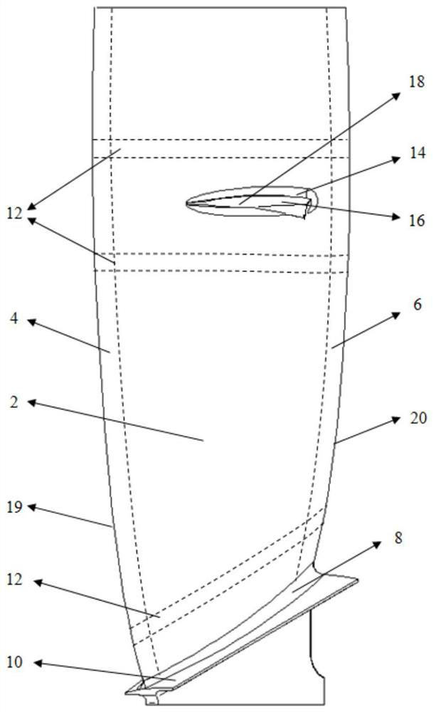
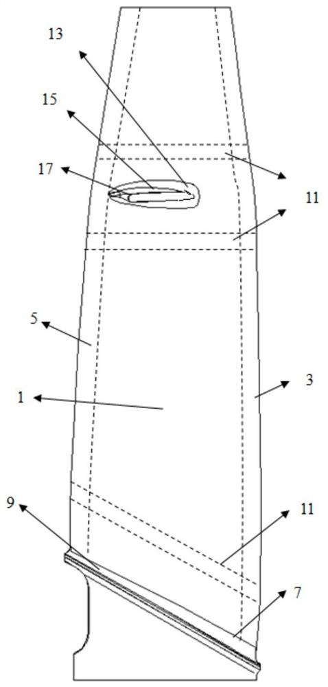
A blade milling-polishing integrated molding method comprises the following steps: step 1, clamping and fixing a fan blade through a clamp I, carrying out milling processing, measuring the fan blade by utilizing a measuring tool after the milling processing is finished, and recording the widths of size out-of-tolerance areas on air inlet edges and air outlet edges; step 2, polishing and partitioning the fan blade according to the measuring results obtained in step 1 and the structure of the fan blade; step 3, carrying out programming and selecting polishing parameters, setting the polishing step pitch, and carrying out polishing track simulation by utilizing motion simulation software; and step 4, fixing the fan blade by utilizing a clamp II, precisely polishing all areas of the fan bladein a force control manner, and effectively removing knife marks and knife vibration characteristics by adjusting the use sequence of polishing tools and abrasive grains. Consequently, the overall processing efficiency can be effectively improved and the overall processing cost can be reduced. Furthermore, the final fan blade processing quality can be guaranteed and the surface roughness grade canbe improved.
Description
technical field [0001] The invention belongs to the technical field of aero-engines, and in particular relates to an integrated molding method of blade milling and polishing. Background technique [0002] As one of the core components of an aero turbofan engine, the blade's dimensional accuracy and surface quality directly affect the starting performance and fatigue life of an aeroengine. The existing large-scale fan blade processing technology is to control the dimensional accuracy through CNC milling and improve the surface roughness through manual polishing. However, since the large fan blade is a thin-walled part with weak stiffness, it is inevitable that there will be tool clearance in the precision milling process, resulting in the fact that the actual processing size does not match the theoretical processing size. [0003] Now the general solution is to control the cutting force as small as possible in the finishing process, so as to reduce the machining deformation,...
Claims
Login to View More Application Information
Patent Timeline
 IPC IPC(8): B23P15/02
CPCB23P15/02
Inventor单坤闵祥禄彭晟尧周雨辰张亚双
OwnerSHENYANG LIMING AERO-ENGINE GROUP CORPORATION