Method and system for obtaining positioning data

a positioning data and method technology, applied in static indicating devices, instruments, manufacturing tools, etc., can solve the problems of wasting resources, adding both to the cost of the final product, and the cost of dedicated hardware is both expensive and complex

Inactive Publication Date: 2013-10-01
QUALCOMM INC
View PDF169 Cites 31 Cited by
  • Summary
  • Abstract
  • Description
  • Claims
  • Application Information

AI Technical Summary

Benefits of technology

[0102]Preferably, the synchronizer is operable to monitor synchronization deviations thereby to reduce a frequency with which repeat synchronizations are carried out.
[0140]detecting the waveform in a manner permitting fixing of the position and outputting the waveform in a manner retentive of the position fixing ability, thereby to provide the computing device with an indication of the position.
[0148]Preferably, the positional element is operable to emit the waveform decodable to fix the position, such that the waveform is decodable at low sampling rate.

Problems solved by technology

The radio or IR only takes care of the wireless connectivity, that is the signaling issue.
The dedicated hardware is both expensive and complex, and is particularly wasteful of resources considering that the calculating power of the main computer is available.
The need for sensors adds both to the cost of the final product, and furthermore provides an unnatural restriction on use in that it does not allow the user to use arbitrary planes, such as a cluttered desk surface, as a working platform.
The complex circuitry and sensors of these solutions require dedicated space.
It is impossible to integrate the solutions to small and hand-held devices for which they have not been explicitly designed, such as PDA's, cellular phones etc.
This issue is also significant with laptops and other movable products where the small size permits a fixed explicitly designed installation but does not allow for the freedom of an arbitrary device.
The installation of hardware components on a PC is tedious and not always reliable.
There is no cross-platform solution currently available: a positioning solution for a touch screen is different from a digital pen solution for the mobile phone market, etc.
The integration of available solutions into an existing product is often ineffective, because of the size and the complexity of the project.
There is no current solution that can be treated as add-in, requiring only software changes.
Support for multiple user applications is difficult and is currently only available where BlueTooth is the communication medium.
Many of the available solutions require substantial power supply.
Some of the technologies are limited to two-dimensional location.
But even those that can manage a third dimension do not currently provide accurate information of the third dimension.
For example a stylus based on electromagnetic detection can be detected when hovering above a screen, but it is not possible to tell accurately how high it is.
There are other drawbacks specific to certain of the technologies.
For instance, IR positioning has difficulties working with direct sun.
Existing acoustic solutions have serious limitations in acoustically noisy environments, in particular in the all-important industrial environment, where ultrasound noise is most common.
Solutions that use wireless protocols as Bluetooth may suffer from protocol collisions, and from interference with other wireless equipment, such as WLAN equipment.
They all have to be attached one way or another to a moving part of the robot and there is no wireless solution that enables the attachment of a sensor on the tip of the moving arm / robot etc.
As always, precision goes along with cost, making precision equipment costly.
Sensors that have high precision over a few meters of distance can cost hundreds of thousands of dollars and are not economically viable for many of the envisaged uses of robots.
It is relatively uncommon, due to the high cost, to have toys in which one unit can be aware of the location of a second unit.
To provide each of the twenty robots with the computing and control power in order to play a game of soccer produces a very expensive and complex solution.
Generally, toy technology has to be provided at low cost and current technology is relatively expensive.
Acoustic—Acoustic devices are relatively expensive.
Only a single unit can be used in the same environment, energy use is relatively high, and the devices are difficult to miniaturize.

Method used


Image

  • Method and system for obtaining positioning data
  • Method and system for obtaining positioning data
  • Method and system for obtaining positioning data

Examples


Embodiment Construction

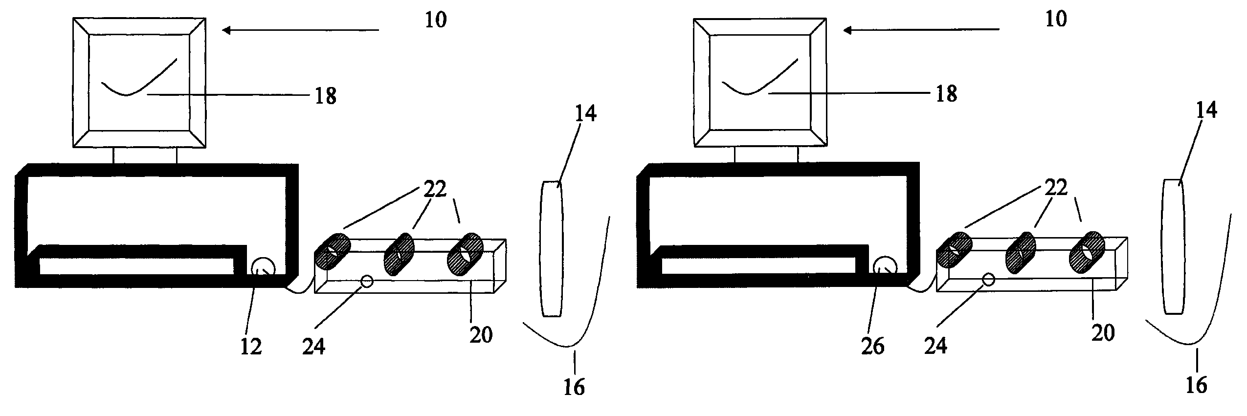
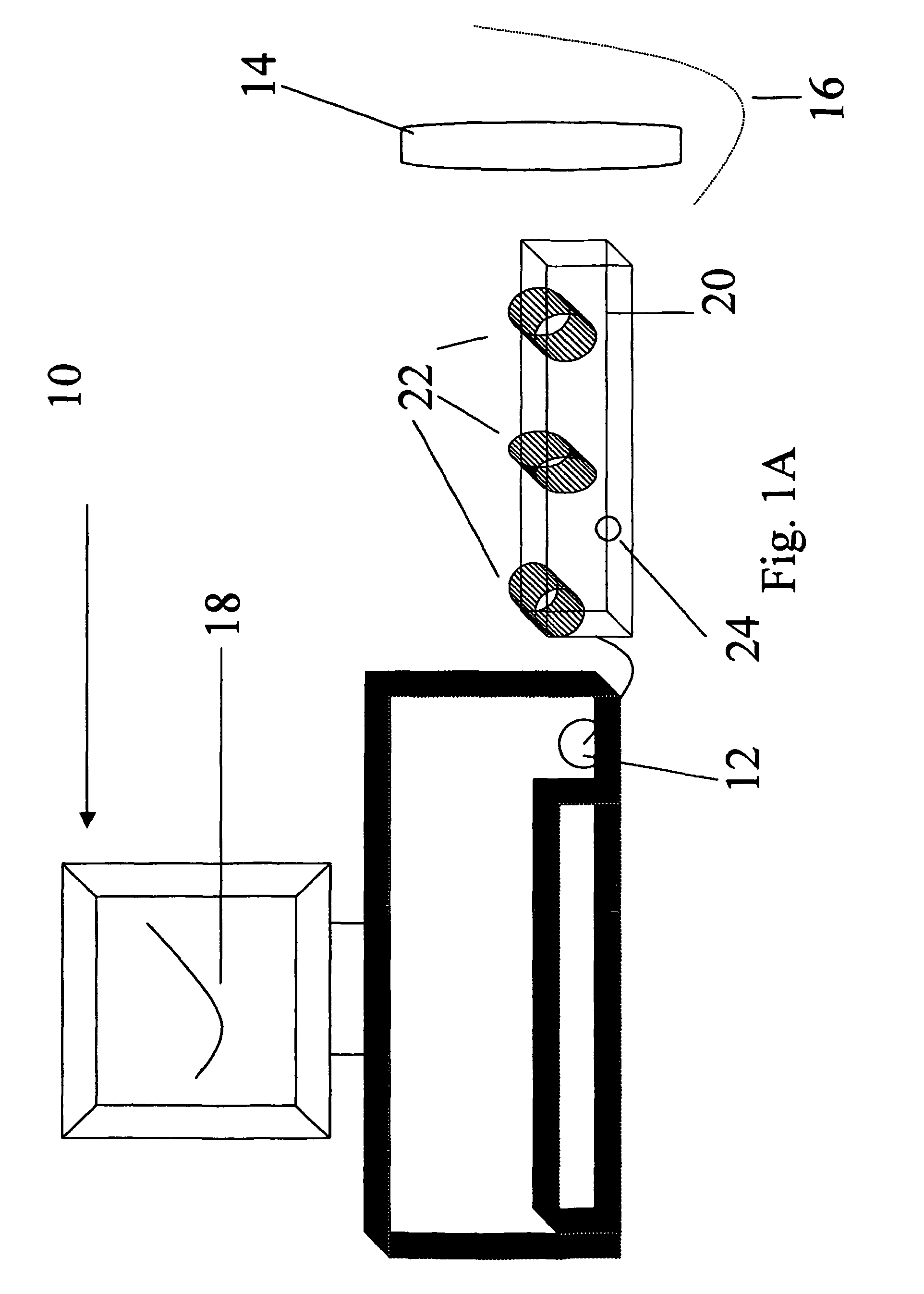
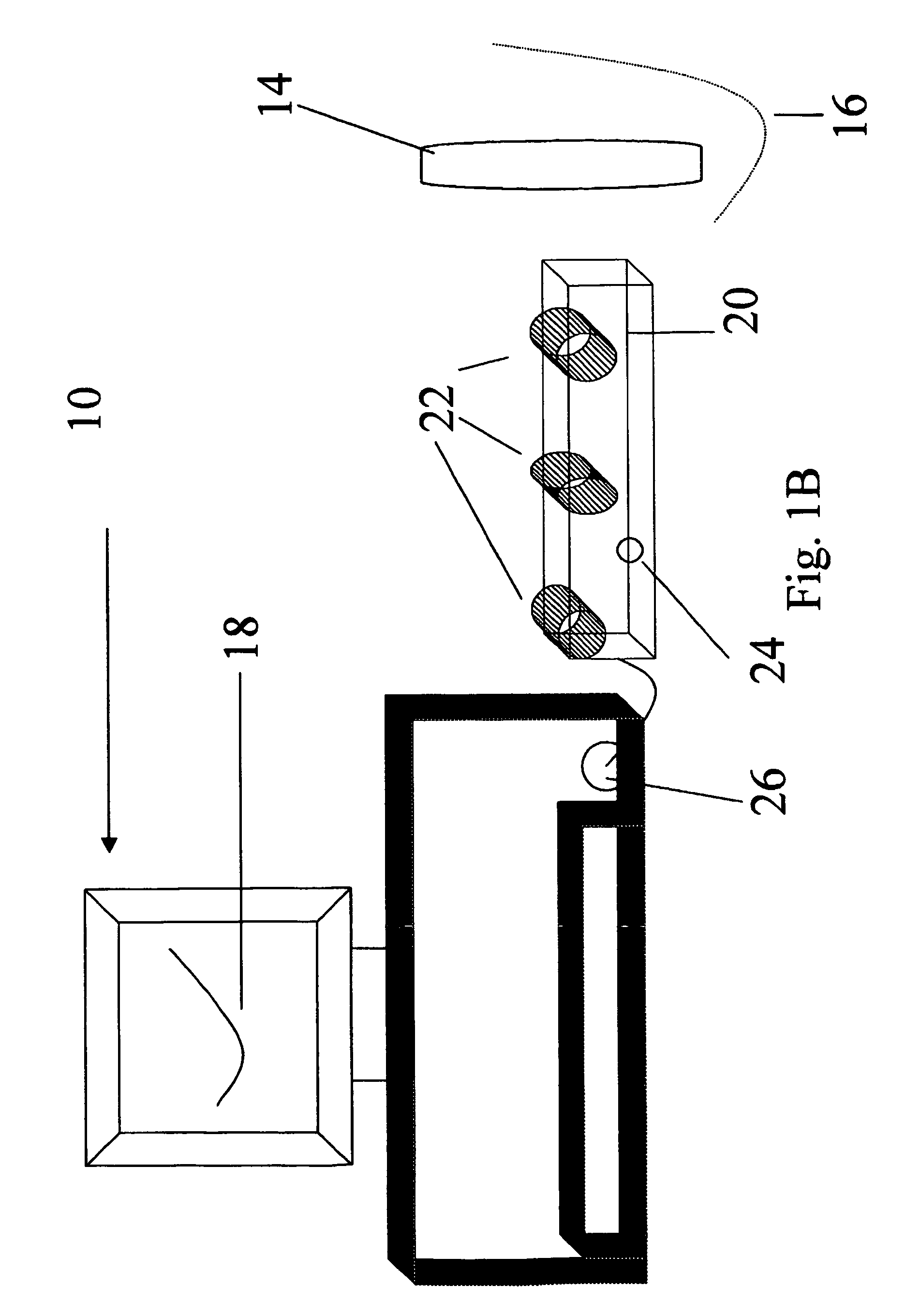
[0199]The present embodiments disclose a system for determining the location of a positional element using continuous wave ultrasound signals and / or using detectors with multiple receivers, whose inputs are multiplexed and entered at a convenient analog input of the computing device with which it is desired to interact. The computing device uses its own resources to demultiplex the signals and determine the location of the pointing device. In an embodiment the signal is a synchronized combination of an ultrasonic and an infrared signal.

[0200]In a further embodiment the detectors may be a standalone device able to process the continuous wave output independently.

[0201]Another aspect of the presently disclosed embodiments concerns the ability to carry out position detection using low processing power to decode the signals.

[0202]The principles and operation of a pointing device and system according to the present invention may be better understood with reference to the drawings and acc...


PUM


Abstract

A position detection system for use in association with computing applications, the system comprising: a positional element for attaining a position and comprising a first emitter for emitting a substantially continuous ultrasonic waveform decodable to fix said position, and a detector arrangement for detecting said waveform in a manner permitting fixing of said position and outputting said waveform for computation, in a manner retentive of said position fixing ability.

Description

RELATED PATENT APPLICATION[0001]This application is a National Phase Application of PCT / IL03 / 00309 having International Filing Date of 14 Apr. 2003, which claims priority from U.S. Provisional Patent Application No. 60 / 372,197 filed 15 Apr. 2002, and U.S. Provisional Patent Application No. 60 / 425,304 filed 12 Nov. 2002.FIELD AND BACKGROUND OF THE INVENTION[0002]The present invention relates to a method and system for obtaining two or three-dimensional co-ordinate data in space and, more particularly, but not exclusively to a positional element and supporting hardware and software for obtaining such co-ordinate information. In general terms one unit is able to determine the position, typically in relation to itself, of another unit.[0003]The field of small space positioning, that is positioning within spaces of a few meters or less, includes a number of fields, principally pointing devices for computer interaction, and robotics and machine control, but also including toys; inventory ...

Claims


Application Information

Patent Timeline
Patent Type & Authority Patents(United States)
IPC IPC(8): G06F3/033G06F3/041G06K11/06G09G3/22G09G3/28G08C21/00G01S5/22G06F3/00G06F3/01G06F3/042G06F3/043G06F3/046
CPCG06F3/011G06F3/014G06F3/0304G06F3/0346G06K9/224G06F3/041G06F3/043G06F3/046G06F3/03545Y10S901/08Y10S901/09G06V30/228G06F17/00B25J9/1664B25J9/1694B25J13/02B25J13/06B25J13/065B25J19/026
Inventor ALTMAN, NATHANELIASHIV, ODED
Owner QUALCOMM INC
Why Eureka
Try Eureka