
Irrigation controller with integral evapotranspiration unit

a technology of irrigation controller and evapotranspiration unit, which is applied in the direction of watering devices, process and machine control, instruments, etc., can solve the problems of irrigation controllers that “piggy back” on existing controllers, water pressure fluctuations that cannot be fully negated, and complicated use of irrigation controllers based on et,

Active Publication Date: 2013-10-01
HUNTER INDUSTRIES
View PDF48 Cites 50 Cited by
  • Summary
  • Abstract
  • Description
  • Claims
  • Application Information

AI Technical Summary

Benefits of technology

The present invention is an irrigation controller that includes a processor and memory for programming. It also has the ability to communicate with a sensor unit containing a second processor and environmental sensors. The controller can receive input from a user through a manually actuable control, such as plant type, soil condition, growth stage, and sprinkler precipitation rate. The programming allows the processor to calculate optimal watering schedules based on the actual ET data and the user-selected information. This invention provides a more efficient and precise way to control irrigation in order to promote plant health and save water.

Problems solved by technology

The amount of water supplied by each sprinkler is largely determined by the size and configuration of its nozzle orifice(s), although variations result from fluctuations in water pressure that cannot be fully negated with regulators.
While such restrictions do save water, they are often arbitrary and do not take into account the watering needs of different types of vegetation in different geographic locations.
Irrigation controllers capable of calculating watering schedules based on ET are typically complicated to use and expensive to buy.
Those schedulers which “piggy back” onto an existing controller have limitations because they can only reduce the existing watering schedules in the base controller.

Method used


Image

  • Irrigation controller with integral evapotranspiration unit
  • Irrigation controller with integral evapotranspiration unit
  • Irrigation controller with integral evapotranspiration unit

Examples


Embodiment Construction

[0016]The entire disclosures of the aforementioned co-pending U.S. patent application Ser. Nos. 10 / 985,425 and 11 / 288,831 are hereby incorporated by reference.

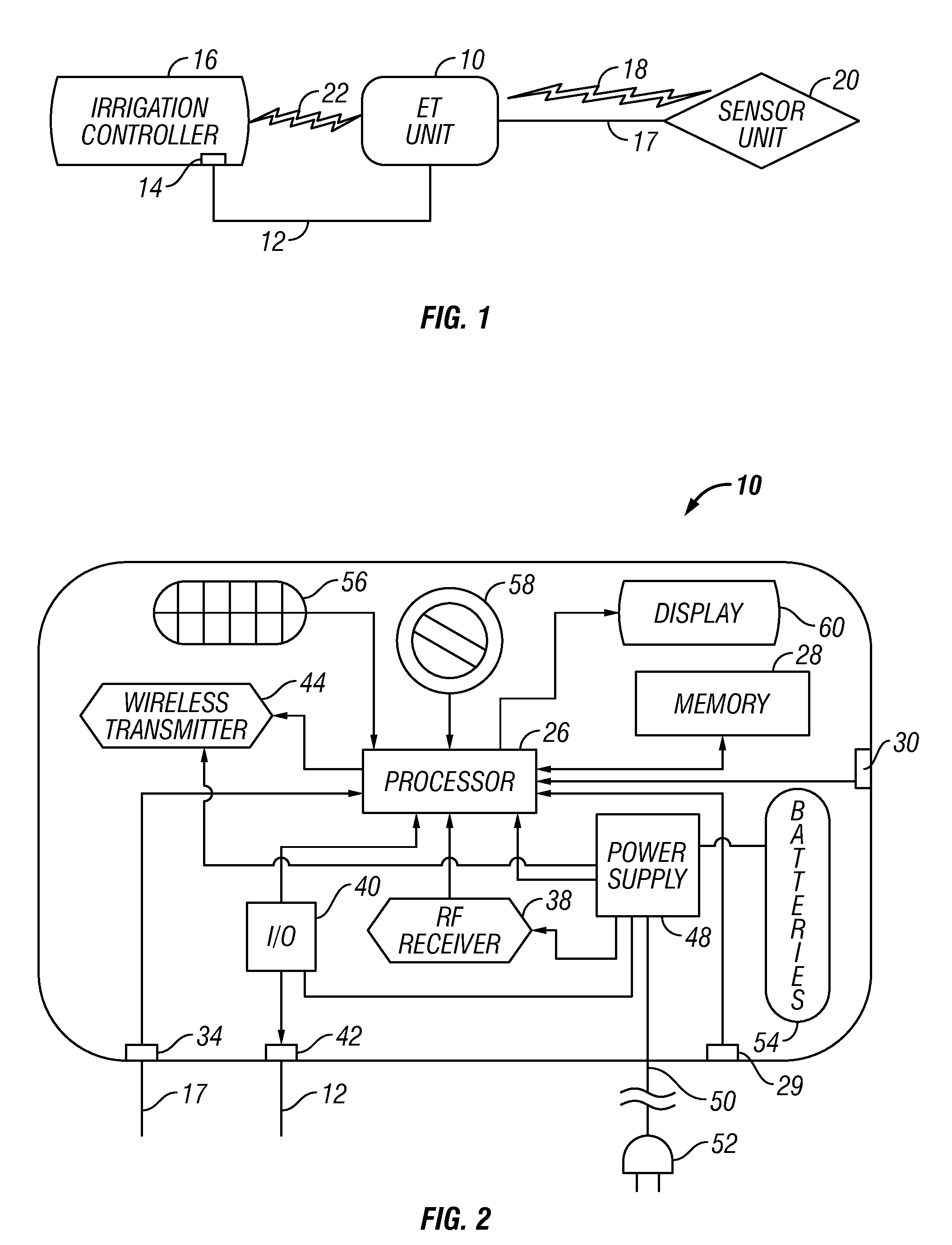
[0017]Referring to FIG. 1, in accordance with an embodiment of the present invention an evapotranspiration (ET) unit 10 is connected, through a hard wired communication link 12 preferably in the form of a wiring harness, to an input port 14 of a separate irrigation controller 16. The ET unit 10 is capable of changing the watering schedules of the irrigation controller 16 based on an actual (as opposed to historical) ET data, and optionally, user inputted ET-related information hereafter described. The ET unit 10 is also connected via hard wired communication link 17 or optional wireless communication link 18 to a remote sensor unit 20 that generates actual ET data. Instead of utilizing the hard wired communication link 12, the ET unit 10 can be connected to the irrigation controller 16 via optional wireless communication link ...


PUM


Abstract

An irrigation controller includes a first processor and a memory for storing programming executable by the first processor. The irrigation controller further includes circuitry that enables a communication link that allows direct communication between the first processor and a sensor unit containing a second processor and a plurality of environmental sensors each capable of generating an actual component of ET data. At least one manually actuable control is operably connected to the first processor for inputting further ET-related information selected from the group consisting of plant type, soil condition, growth stage and sprinkler precipitation rate. The irrigation controller further includes programming that enables the first processor to calculate optimum watering schedules based upon the actual ET data and the ET-related information including increases and decreases in the frequency and / or length of ON times for at least one station.

Description

CROSS REFERENCE TO RELATED APPLICATIONS[0001]This application is a continuation-in-part of U.S. patent application Ser. No. 10 / 985,425 filed Nov. 9, 2004 of LaMonte D. Porter et al. entitled “Evapotranspiration Unit Connectable to an Irrigation Controller,” which issued as U.S. Pat. No. 7,853,363 on Dec. 14, 2010. This application is also a continuation-in-part of, and claims priority from, U.S. patent application Ser. No. 11 / 288,831 filed Nov. 29, 2005, now U.S. Pat. No. 7,412,303 granted Aug. 12, 2008, of LaMonte D. Porter et al. entitled “Evapotranspiration Unit for Re-Programming an Irrigation Controller.” This application is also a continuation of the similarly entitled U.S. patent application Ser. No. 12 / 176,936 filed Jul. 21, 2008, of LaMonte D. Porter, which is expected to issue as U.S. Pat. No. 7,877,168 on Jan. 25, 2011.FIELD OF THE INVENTION[0002]The present invention relates to electronic irrigation controllers that selectively actuate valves to supply water to sprinkler...

Claims


Application Information

Patent Timeline
Patent Type & Authority Patents(United States)
IPC IPC(8): G05D11/00A01G27/00
CPCA01G25/167Y02A40/10
Inventor PORTER, LA MONTE D.WOYTOWITZ, PETER J.SHEARIN, CHRISTOPHER M.
Owner HUNTER INDUSTRIES
Learn More