Bearing of a breaking device tool

a technology of breaking device and bearing bushing, which is applied in the direction of manufacturing tools, mechanical machines/dredgers, portable drilling machines, etc., can solve the problems of material breaking, difficult and slow to change a worn bearing bushing in working site conditions, etc., and achieves simple operation, small manufacturing cost, and easy insertion

Inactive Publication Date: 2013-10-08
WILLIAMS FR JOHN +1
View PDF27 Cites 4 Cited by
  • Summary
  • Abstract
  • Description
  • Claims
  • Application Information

AI Technical Summary

Benefits of technology

[0009]An advantage of the invention is that the bearing bushing can be easily inserted in the axial direction to its place in the bearing space, since there is a clearance fit between the bearing space and the bearing bushing. No special pressing tools or the like are required for the mounting, but the bearing bushing can be inserted into the bearing space with manual force. Further, the bearing bushing is a simple utility item the manufacturing costs of which are small.
[0010]The idea of an embodiment of the invention is that the bearing bushing is prevented in the axial direction from getting out of the bearing space by means of one or more prelocking members. The prelocking member keeps the bearing bushing temporarily in place until the bearing bushing is deformed and actually attached to the bearing space.
[0011]The idea of an embodiment of the invention is that at least one bearing space is positioned at the lower end of the breaking device on the side of the tool in such a way that the bearing space is open downwards in the axial direction. Thus, the bearing bushing is insertable in the axial direction from below to its place in the bearing space without having to disassemble the lower frame of the breaking device. For changing, only the tool needs to be detached. An advantage of this embodiment is that it is quick and simple to change the bearing bushing. Further, since there is no need to disassemble structures of the breaking device, the changing may also take place in dirty working site conditions. As it is possible to change the bearing bushing in the working site, the interruption in the use of the breaking device can be as short as possible.
[0012]The idea of an embodiment of the invention is that the breaking device comprises a tool bushing comprising a bushing frame the inner circle of which forms a bearing space for the bearing bushing. The bushing frame may be immovably attached to the frame of the breaking device by means of one or more locking means. The bearing bushing is arranged to be deformed during the operation of the breaking device in such a way that it is pressed against the inner periphery of the bushing frame in the radial direction. The strength of the bushing frame is dimensioned to be greater than that of the bearing bushing so that substantially only the bearing bushing is deformed by the effect of stress waves. An advantage of this embodiment is that the bushing frame and the bearing space in it may be detached and changed, if required. Further, the tool bushings of the present breaking devices already in use may be replaced with tool bushings according to this embodiment, after which it will be easier to change the bearing bushings in the future.
[0013]The idea of an embodiment of the invention is that the bearing space is formed directly in the frame of the breaking device. Thus, the bearing bushing is arranged to be deformed against the frame of the breaking device during the use of the device. An advantage of this embodiment is that the breaking device does not need a separate bushing frame to form a bearing space. Thus, the diameter of the hole to be made around the tool in the breaking device frame may be smaller than when a separate detachable bushing frame is used, which reduces the manufacturing costs. In addition, there is no need to manufacture a bushing frame. Furthermore, the bearing space formed in the breaking device frame is particularly firm, whereby it can well receive the compression stress of the bearing bushing deformed during the use.
[0014]The idea of an embodiment of the invention is that the bearing bushing is of bearing bronze. Bearing bronze suits well to be used as the slide bearing of a breaking device tool, because it is deformed relatively easily due to the effect of stress waves, still having sufficient yield strength so that deformation causes compression stress in it, which keeps the bearing bushing in place in the bearing space due to the friction between the bearing bushing and the bearing space. Further, an advantage of bearing bronze is that it endures also short-term dry use without getting damaged when, for some reason or other, there is no lubricant film between the bearing bushing and the tool.

Problems solved by technology

At the same time, the tool is pressed against the material to be broken, whereby the effect of the stress waves and pressing causes the tool to penetrate into the material to be broken, which results in breaking of the material.
A problem with known solutions is that it is difficult and slow to change a worn bearing bushing in working site conditions.

Method used


Image

  • Bearing of a breaking device tool
  • Bearing of a breaking device tool
  • Bearing of a breaking device tool

Examples


Embodiment Construction

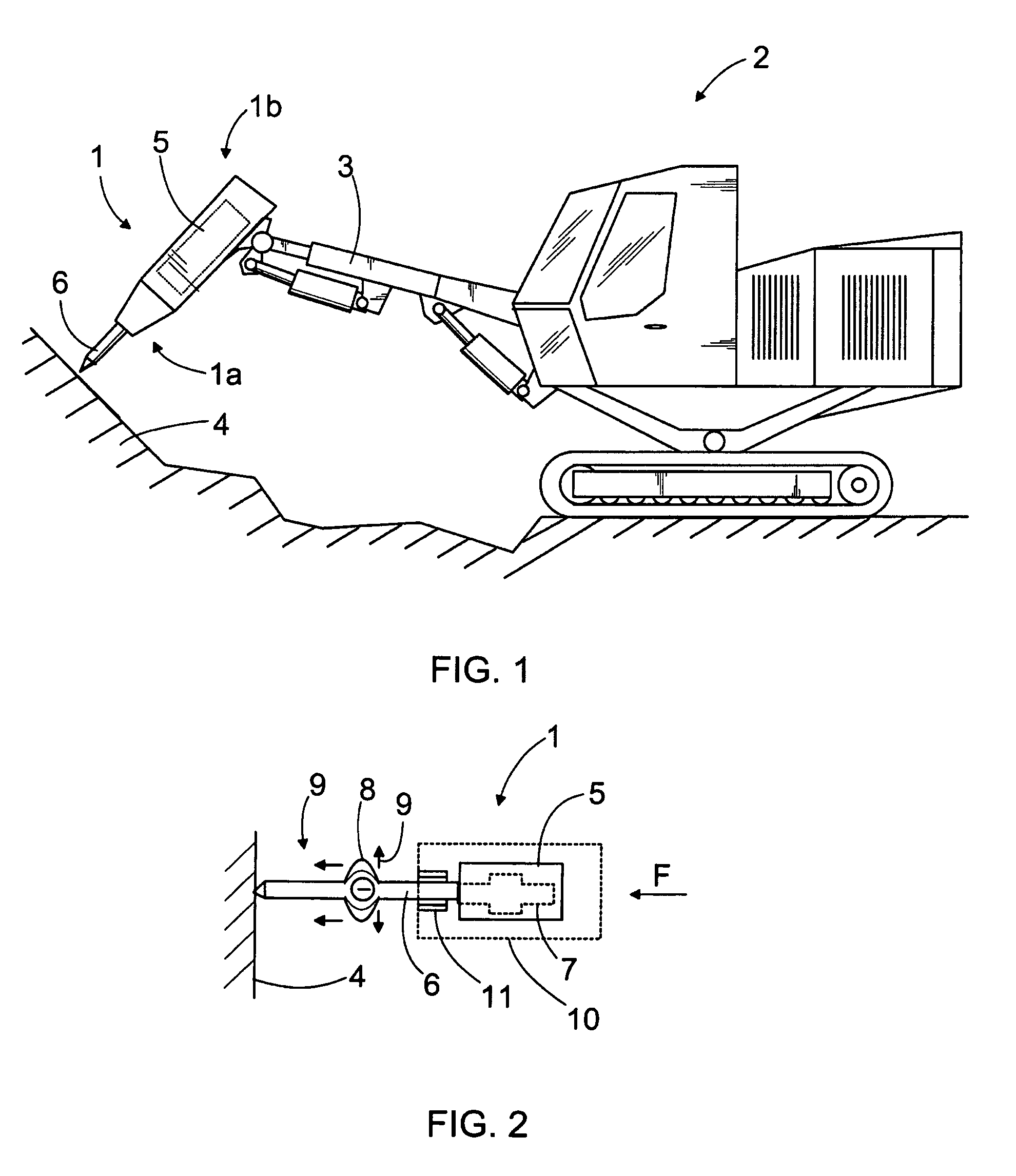
[0032]In FIG. 1, a breaking hammer 1 is arranged on a boom 3 in an excavator 2. The breaking hammer 1 may be a hydraulic, pneumatic or electric device. The breaking device 1 is pressed by means of the boom 3 against material 4 to be broken at the same time as compression stress pulses may be given to a tool 6 connected to the hammer with a percussion device 5 in the hammer, and the tool 6 transmits the stress pulses to the material to be broken. The percussion device 5 usually comprises a reciprocating percussion piston striking a percussion surface at the upper end of the tool 6. In some cases, the percussion element may be an element other than a reciprocating percussion piston. Further, there may be a protective casing around the breaking hammer 1, protecting it against damages and impurities.

[0033]It can be noted that in this application the lower part 1a of the breaking hammer refers to the end on the side of the tool 6, while the upper part 1b of the breaking hammer refers to ...


PUM

PropertyMeasurementUnit
densityaaaaaaaaaa
thicknessaaaaaaaaaa
thicknessaaaaaaaaaa

Abstract

The invention relates to a method for fitting a breaking device tool with a bearing, a breaking device and a tool bushing. The tool of the breaking device is fitted with a bearing with at least one bearing bushing manufactured of bearing material and arranged in a bearing space. There is a clearance fit between the bearing bushing and the bearing space, whereby the bearing bushing is insertable into the bearing space by manual force. During the use, compression stress pulses are given to the tool with a percussion device, whereby stress waves travel in the tool, which waves generate on the tool surface a movement in the direction of its perpendicular. This movement is transmitted to the bearing bushing, and it deforms the bearing bushing in the radial direction in such a way that the bearing bushing is pressed against the bearing space.

Description

RELATED APPLICATION DATA[0001]This application claims priority under 35 U.S.C. §119 and / or §365 to Finish Application No. 20065775, filed in Finland on Dec. 5, 2006, the entire contents of which are incorporated herein by reference.BACKGROUND OF THE INVENTION[0002]The invention relates to a method for fitting a breaking device tool with a bearing, a breaking device and a tool bushing used for a bearing. The breaking device comprises at least a frame, a tool and a percussion device. By means of a percussion element in the percussion device, compression stress pulses are generated in the tool, which transmits them further to material to be broken. In a bearing space around the tool a bearing bushing is arranged, a sliding surface on the inner periphery of the bearing bushing fitting the tool with a bearing to be movable in the axial direction of the tool. The object of the invention is described in more detail in the preambles of the independent claims.[0003]A breaking hammer is a bre...

Claims


Application Information

Patent Timeline
Patent Type & Authority Patents(United States)
IPC IPC(8): B25D17/08
CPCB25D17/08B25D2222/31Y10T29/49826B25D2250/331B25D2222/54E02F3/36E02F5/16
Inventor KAHRA, OSSI
Owner WILLIAMS FR JOHN
Why Eureka
Try Eureka